
Ok, so the front suspension is now starting to take way longer than I anticipated. I’m 6 sessions in and still not completed what I thought was a simple part of the build. A lot of the problem is that I’m not getting many long sessions in. It just goes to show how difficult it is to build a kit car when there are other things going on in your life…
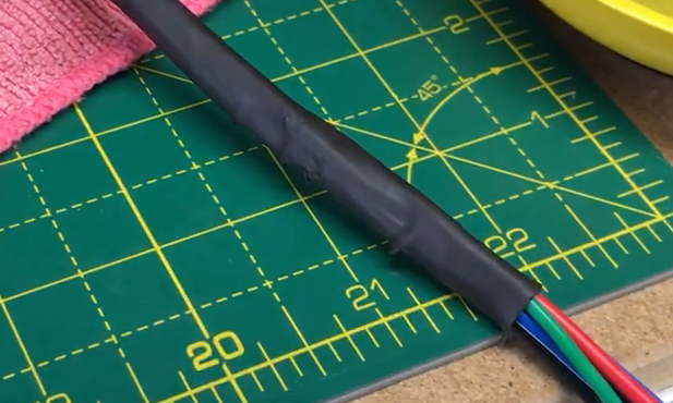
Layers of Heatshrink
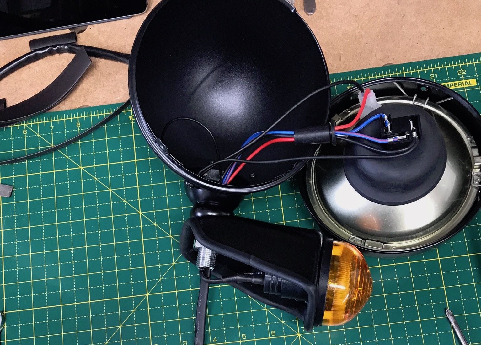
I’d finished the IVA strips around the indicator pods yesterday and was determined to get the headlamps on the car today.
I am following Daniel French’s procedure of using heat shrink for the wiring of the headlamps and indicators. However, the moulding on the back of the indicator is different to that in Daniel’s post. The one’s I have have got a wider protrusion sticking out of the back of the moulding. 10mm heatshrink just isn’t going to go over the top.
I checked my box of heatshrink…
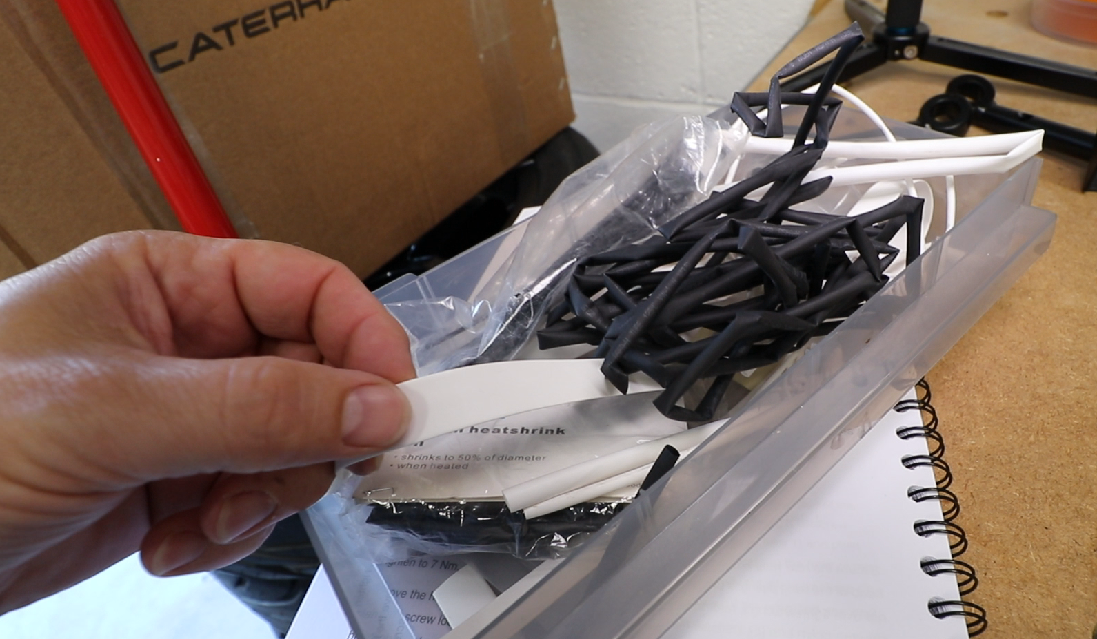
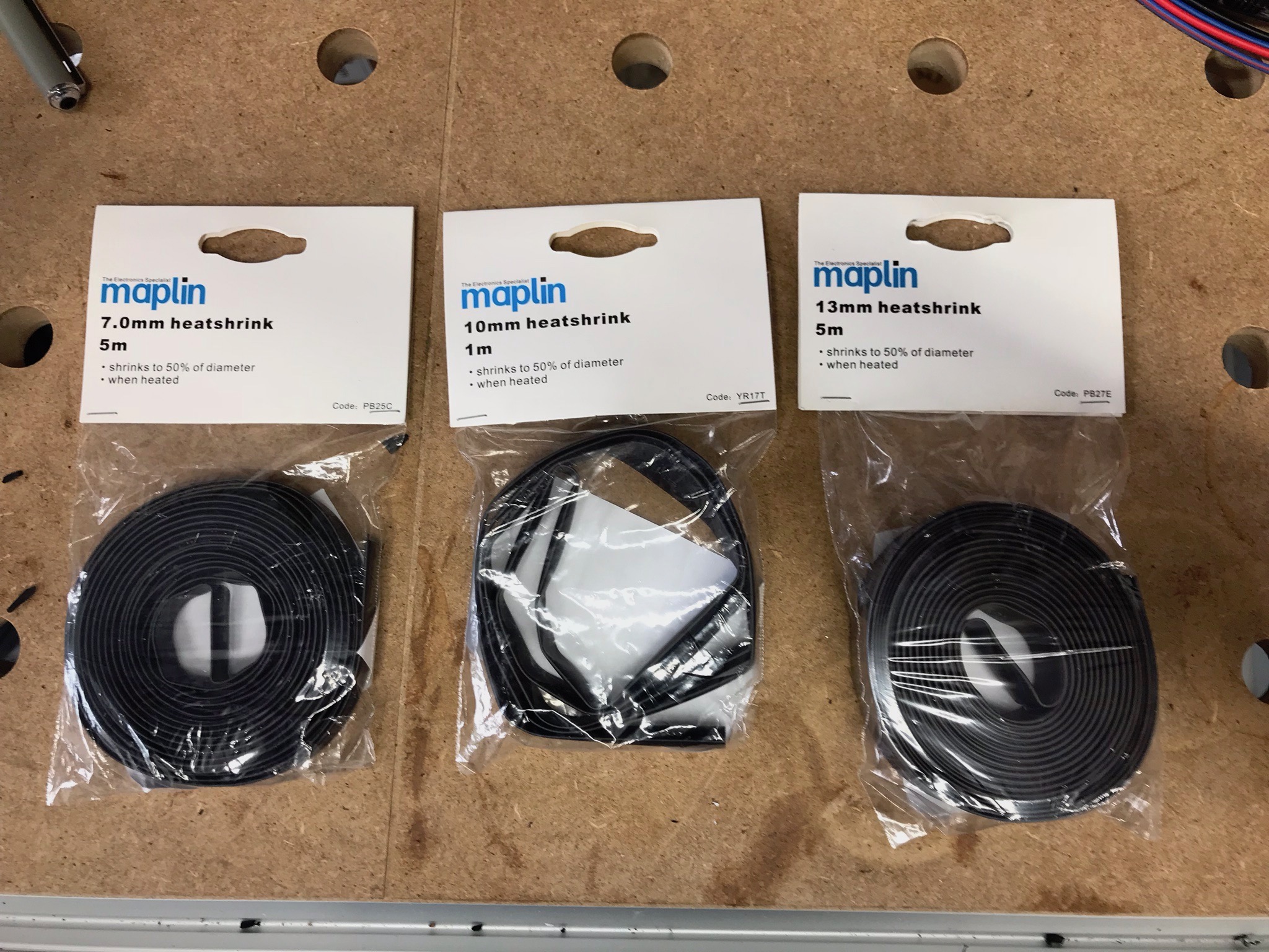
… but I didn’t have any of the right size in black. So, a trip to Maplin for some heatshrink and while I was there I popped into B&Q and got some pipe lagging to protect the chassis.

While on the topic of pipe lagging… I bought both 15mm and 22mm just because I wasn’t sure what would work best on different sections of the chassis. It seems to be that the 15mm is probably the better option in the end, and now measuring the main chassis rails at just over 19mm that seems to make sense – the 22mm lagging flops around a bit on the rails, though can be more useful for the bodywork sides.
Back to the Headlamp Assemblies
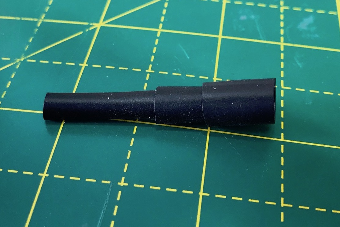
I decided I needed a slightly different approach than Daniel’s heatshrink on the back of the indicator. With the 7mm, 10mm and 13mm heatshrink I’d bought from Maplin I would put a layer of each covering the bigger protrusion and the wires… stepping down from 13mm to 10mm and then finally to 7mm.
I had started writing this post with the intension of describing my process in much greater detail than what you see here, and also with more pictures than Daniel had included – his post is great but there’s this new heatshrink approach and there’s a couple of areas where I think Daniel’s pictures could be added to (no offence Daniel – I really appreciate the work you did in figuring this out in the first place).
However, that was taking way too much time and I was getting behind with these posts. So, that info will have to wait for an addendum post – just like Daniel did!
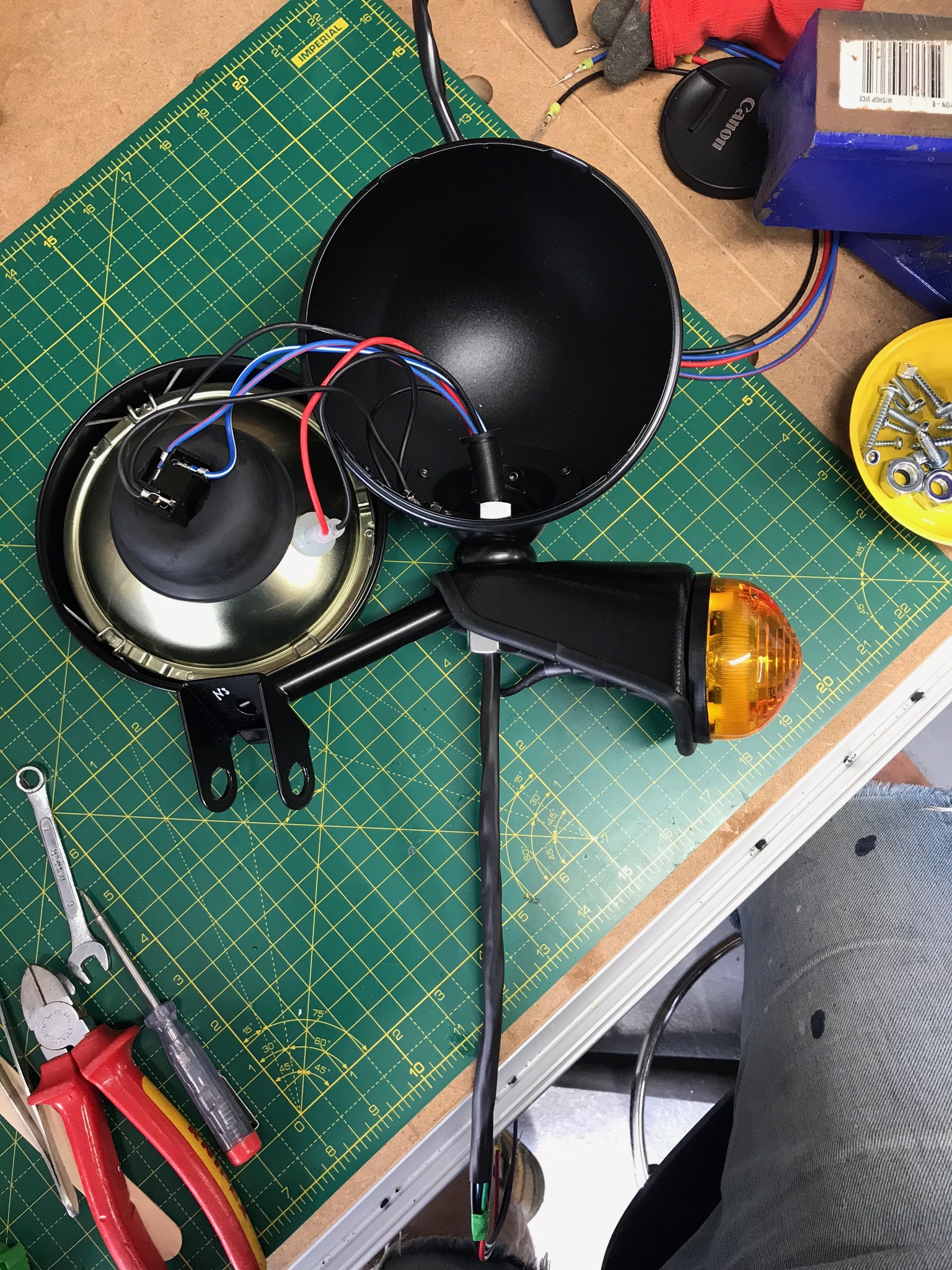
The short version is therefore that I ended up with a headlamp assembly looking like this:
One Big Hiccup
I had one hiccup during the assembly, and that was not to include the headlamp stem in the stack of components that need to have the various wires fed through them. I got the whole thing assembled only to realise that the headlamp stem was missing and wouldn’t go into the stack of bits where it needed to be. Doh! What was I thinking!
So, I had to take the 300mm of 10mm heat shrink off (the heatshrink that runs out of the bottom of the picture above), re-thread all the wires into and out of the headlamp again and make sure I got the stem in the right place in the assembly stack. Then I could re-heatshrink the long wires again with the 10mm heatshrink.
Threading The Stem
Another step I’ll pull out from the detailed description is how I threaded the heatshrunk cable assembly down through the oval hole in the headlamp stem. The first one I did took ages. I was using rubber lubricant and lots of force but it just took forever to feed through the oval hole (there’s an oval hole in the side of the stem/tube that runs out of the bottom right of the picture below). I tried all sorts of angles, twisting as it went in (which helped a bit) and trying to feed it in from the rear of the oval. The heatshrink just kept getting rucked as I fed it into the stem. I even considered pulling the whole think apart and putting 7mm heatshrink on instead – but a quick test of that showed it was really going to work – the heatshrink was too tight.
headlamp stem
Eventually I got it through, but I ended up chewing up the heat shrink in places. I think it will be fine from a water ingress perspective but it didn’t look so great.
On the second stem I spent some time making sure the oval hole was free from any burs. I didn’t find any but I ran a file around the aperture anyway and probably took off some of the powder coat along the way. I also ran a file up the inside of the stem just to make sure there weren’t any burs there too.
The second heat shrink assembly then went through the oval in its stem in about 60 seconds. I couldn’t believe my luck. I had made a fresh brew and was steeling myself for a big job but it turned out to be a non-event.
Headlamp and Indicator Assembly Time
In the end this job took all of a Sunday afternoon for the two headlamp assemblies. What with screwing up on leaving out the stem from the first assembly and then the heatshrink not going down the stem smoothly, it took about 3 and 1/2 hours to get the first assembly done.
The second stem took 45 minutes. No fuss no hiccups.
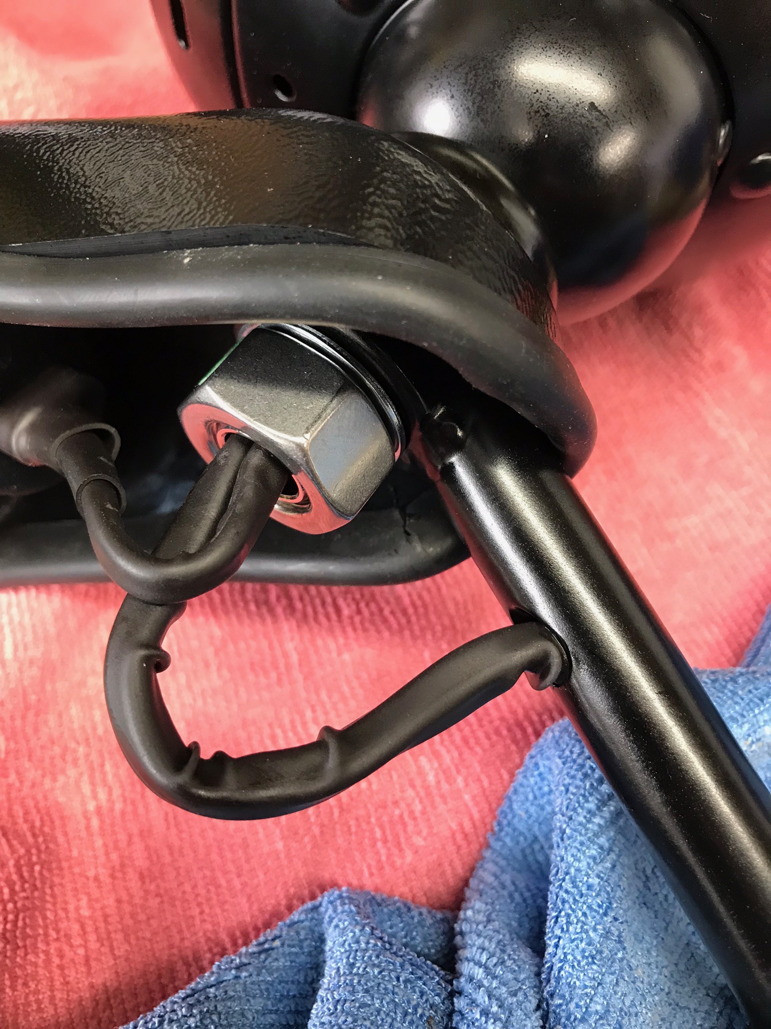
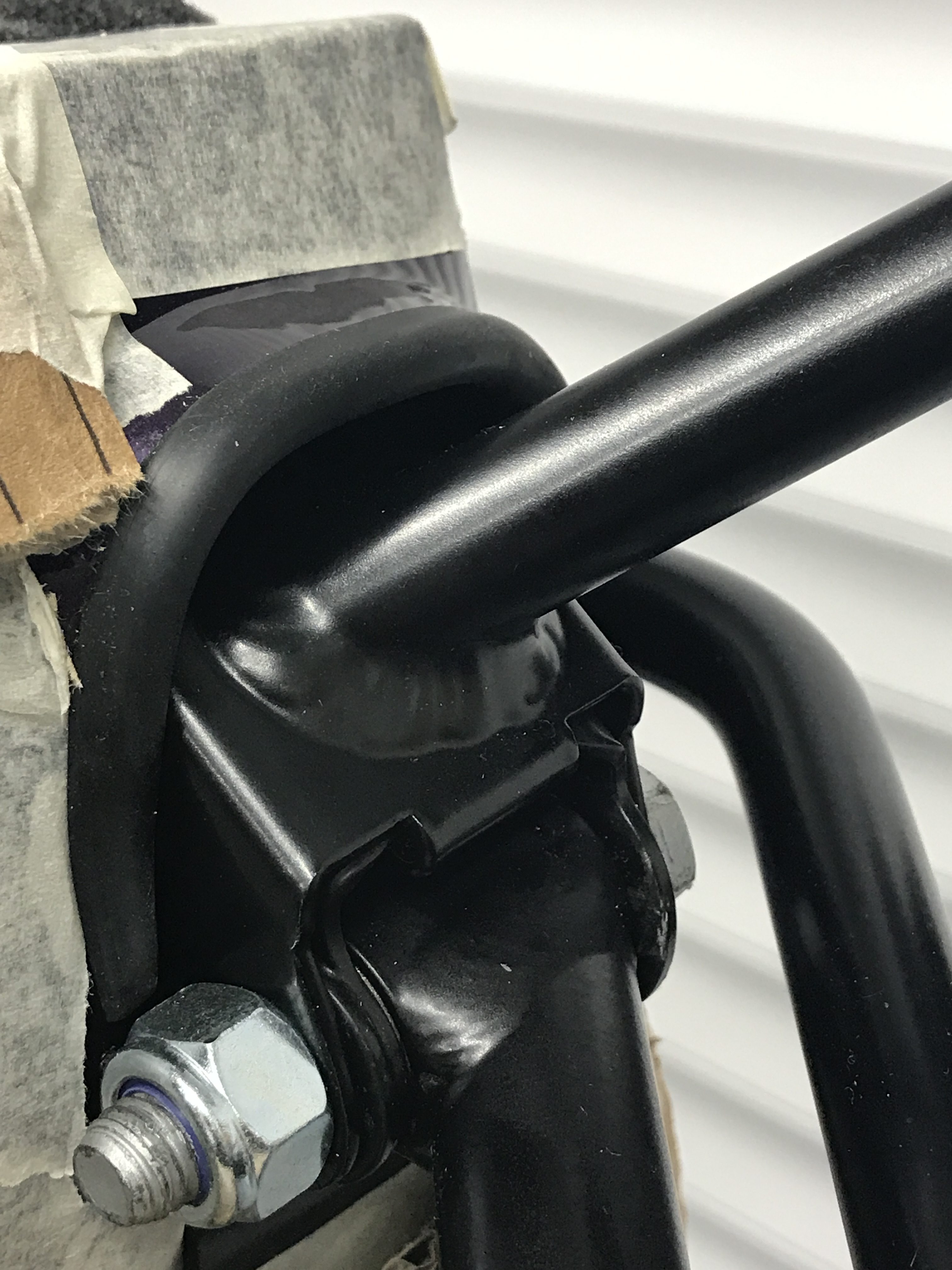
Then it was about 15 minutes to fit the two assemblies to the car. They turned out to be a little trickier than I’d expected… mainly because the angle at which the stem comes down and meets the chassis mount means that the cables don’t have enough clearance to feed through the chassis mount hole from the end of the stem as the as the wires come out of the stem ( I know a picture of this would be useful but I don’t have one – sorry). You have the chassis mount, the headlamp assembly and the upper wishbone all meeting at the same point and fixed with the same bolt. In the end I bent the lug on the bottom of the headlamp stem so that the assembly could approach the chassis mount at a wider angle. It wasn’t how I hoped it would be but there seemed no other choice.
This is what the headlamp assembly, chassis mount and upper wishbone all look like when the come together and attached with a bolt.
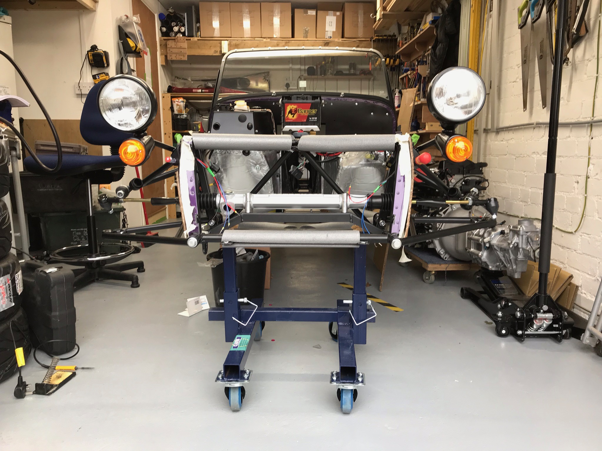
The whole thing now looks even more like Brum…
Grommets
A final word on this task. Grommets. The manual calls for a grommet to be fitted to the oval hole in the headlamp stem down tube. The 10mm heatshrink and cables were such a tight fit through the hole that I couldn’t see any way at all to get a grommet in there too.
I’ve also seen bloggers put a grommet in the chassis mount hole before the stem gets attached, but I just don’t see how that can be an IVA fail not to have a grommet there. Again, a picture would be useful here but I don’t have one.
Note to self… take more pictures.
In the end I didn’t put any grommets into the headlamp stem down tube or the chassis mount. Time will tell if this is a mistake.

Leave a Comment