
A short session today, I managed to get a couple of hours in between, and then after, my evening meetings.
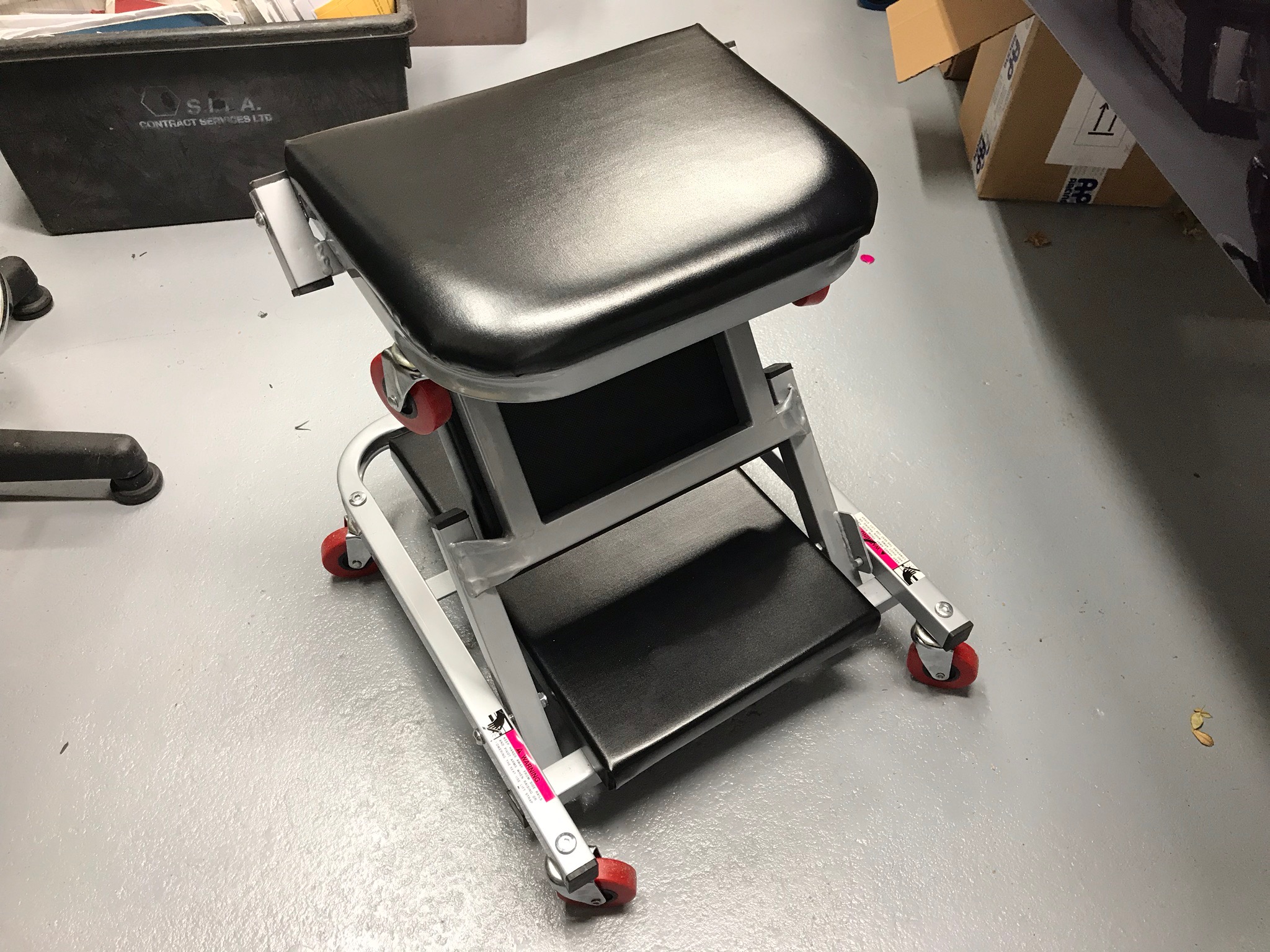
Stool / Creeper
Firstly: new toys. I’d read in a number of blogs that a number of builders had got on well with folding stool/creepers. After spending a lot of Sunday bent over the car looking at headlamp fixings and front suspension my back was in a poor state that night. So, come Monday I ordered a folding stool/creeper from Amazon and which turned up today, Tuesday.
It got put to work staight away on the the dampers as I sat on the stool. Worked really well and pleased with the purchase at the moment.
The creeper can be found at the link below (for as long as this link works):
Description:
- Length: 40inch
- Wheels: 6 x 2.5inch
- 120kg capacity!
- Padded headrest
- Mechanics Creeper and stool in 1
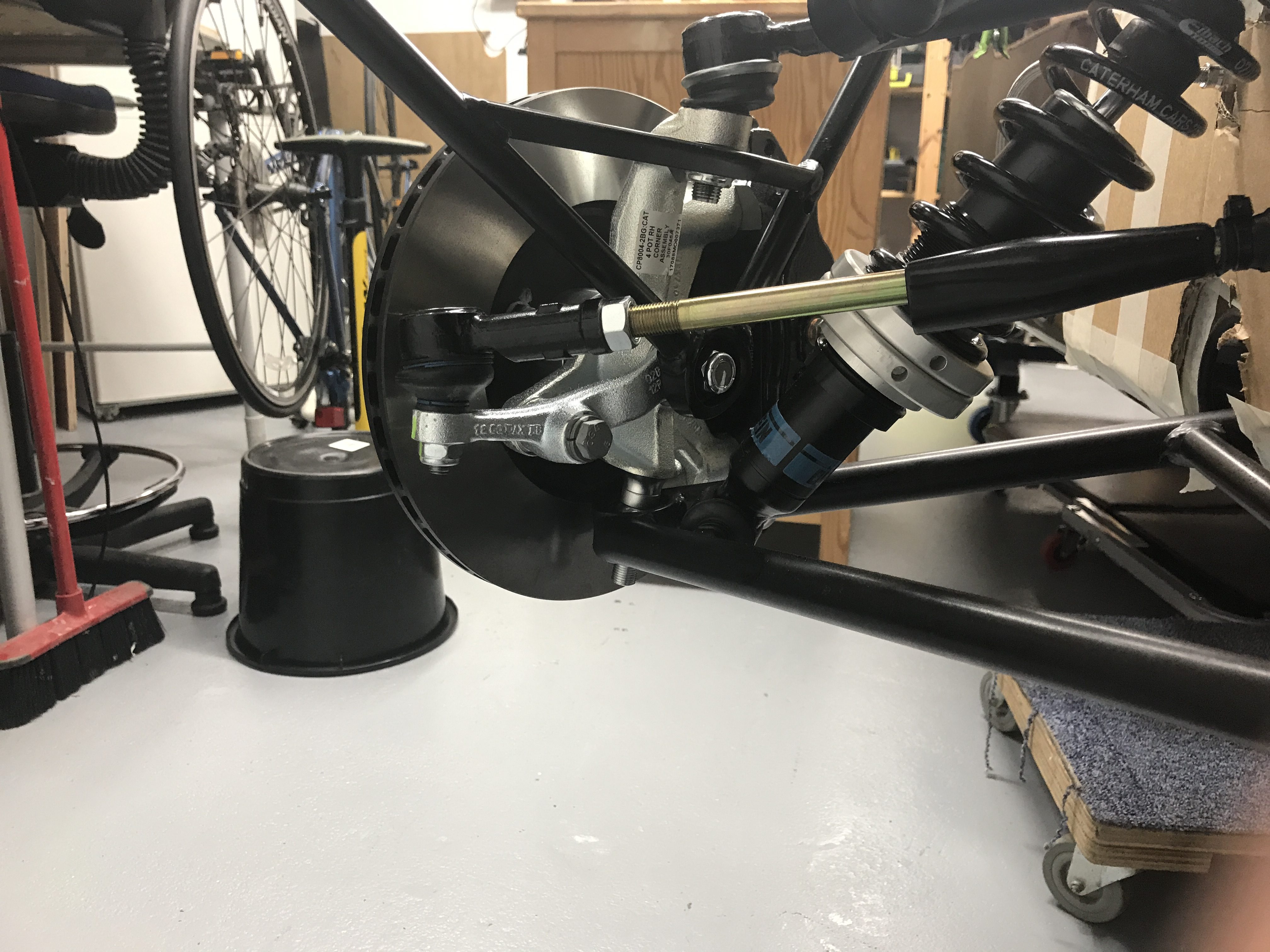
Front Dampers
I was a little concerned about which way up the dampers should be inserted. The obvious way is to make the Bilstein writing be the right way up – i.e. readable (this is a 420 “R” so has adjustable Bilsteins). There seems to be a lot of debate about the pro’s and con’s of putting the dampers in both “the right way up” and “upside down”. It also seems that the R500 install has them “upside down”. However, the Caterham recommended way for at least the 420 is to have them with the writing readable and therefore at the bottom of the damper – the “right way up”. I decided to go this way and only to think about the other option when I know a bit more about what I’m doing.
After that decision they went in pretty straightforwardly. There are spacers to fit in the top and bottom of each damper. All the same size and there are 4 spacers that fit the bill in the suspension pack. Don’t forget the copper ease.
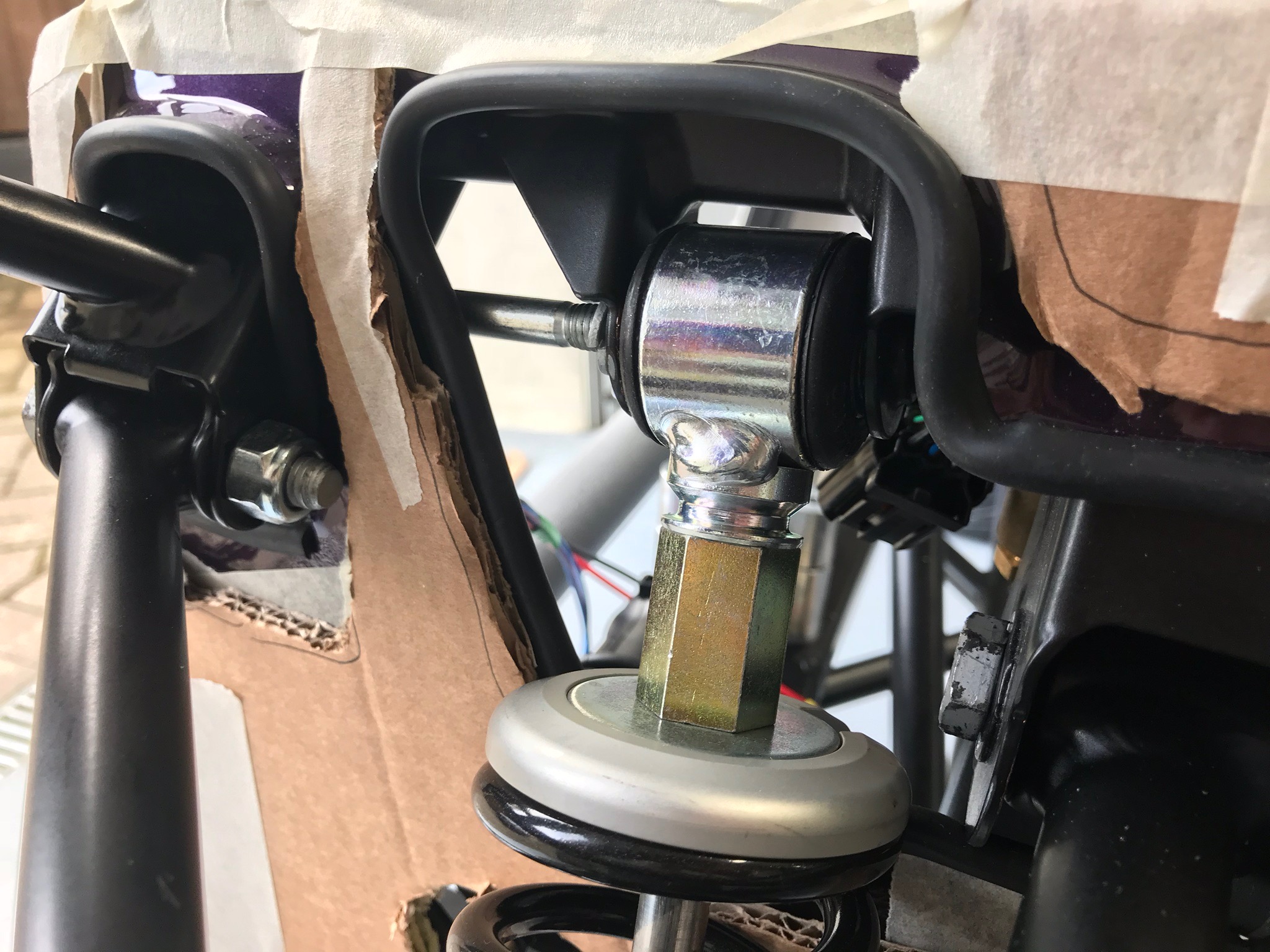
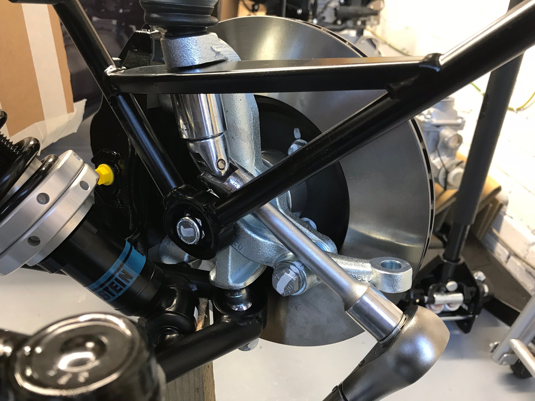
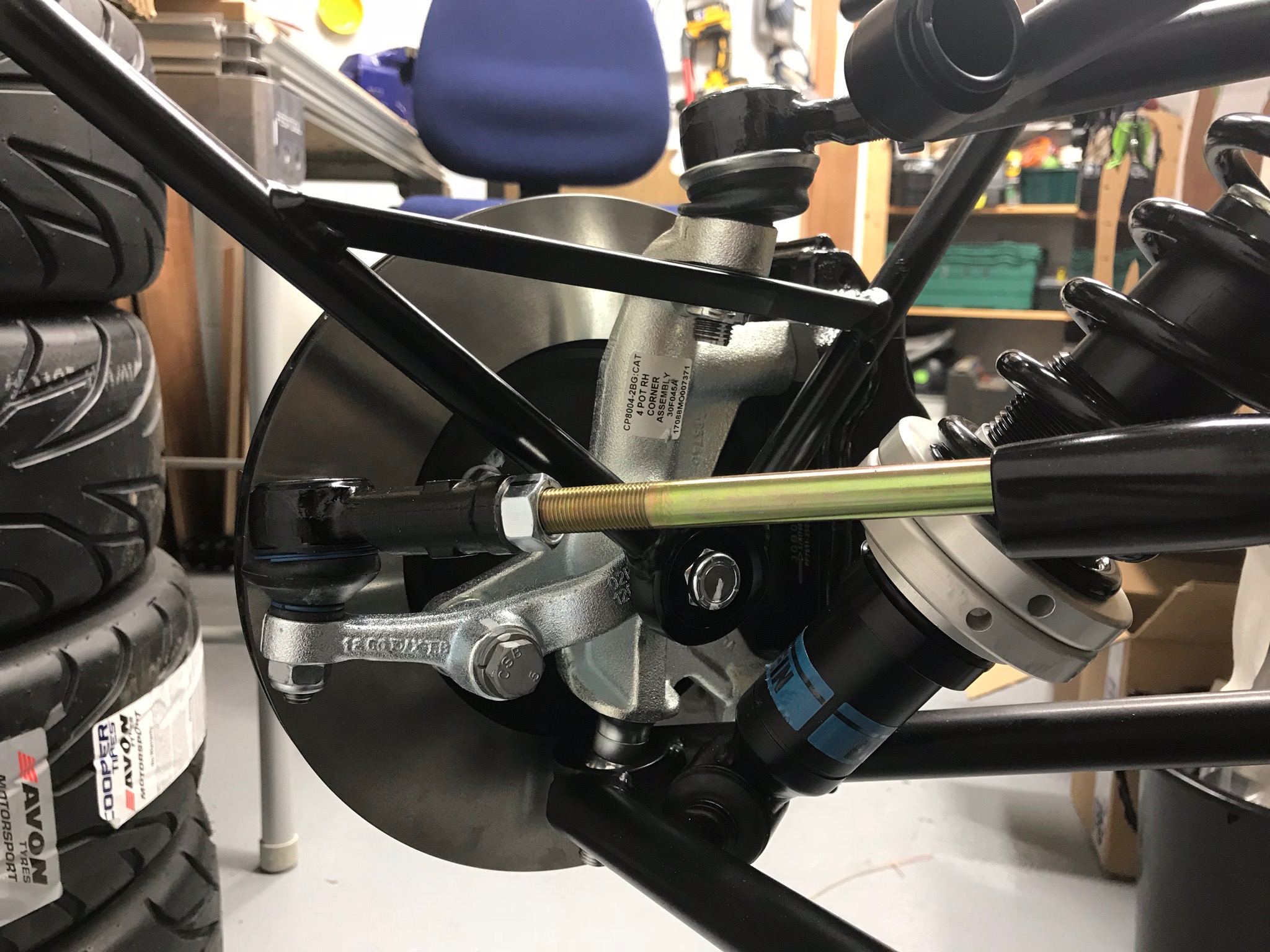
I will make one final comment on the dampers and that is to add the considerable number of people commenting on the blogosphere about how difficult it is to firstly get out, and the get back in, the top damper bolt. It is a cap head bolt with a 6mm hex bit needed to tighten/untighten. As you can see in the picture above the bolt is very close to the bodywork. But what you can’t see is that it also gets very close to an inside chassis member before it can be fully extracted. Both issues add up to meaning that you can’t get a socket allen key or ratchet on the cap head. I tried a 3/8th’s socket and wobble bar combo but there just isn’t enough room. In the end I cut down a 6mm allen key almost all the way down to the shaft and used that and some pliers to turn the bolt, flat-by-flat, both out and the back in again with the damper now inserted. Fortunately, the bolt goes in at a bit of an angle and therefore as you turn it, it will pull itself out and in.
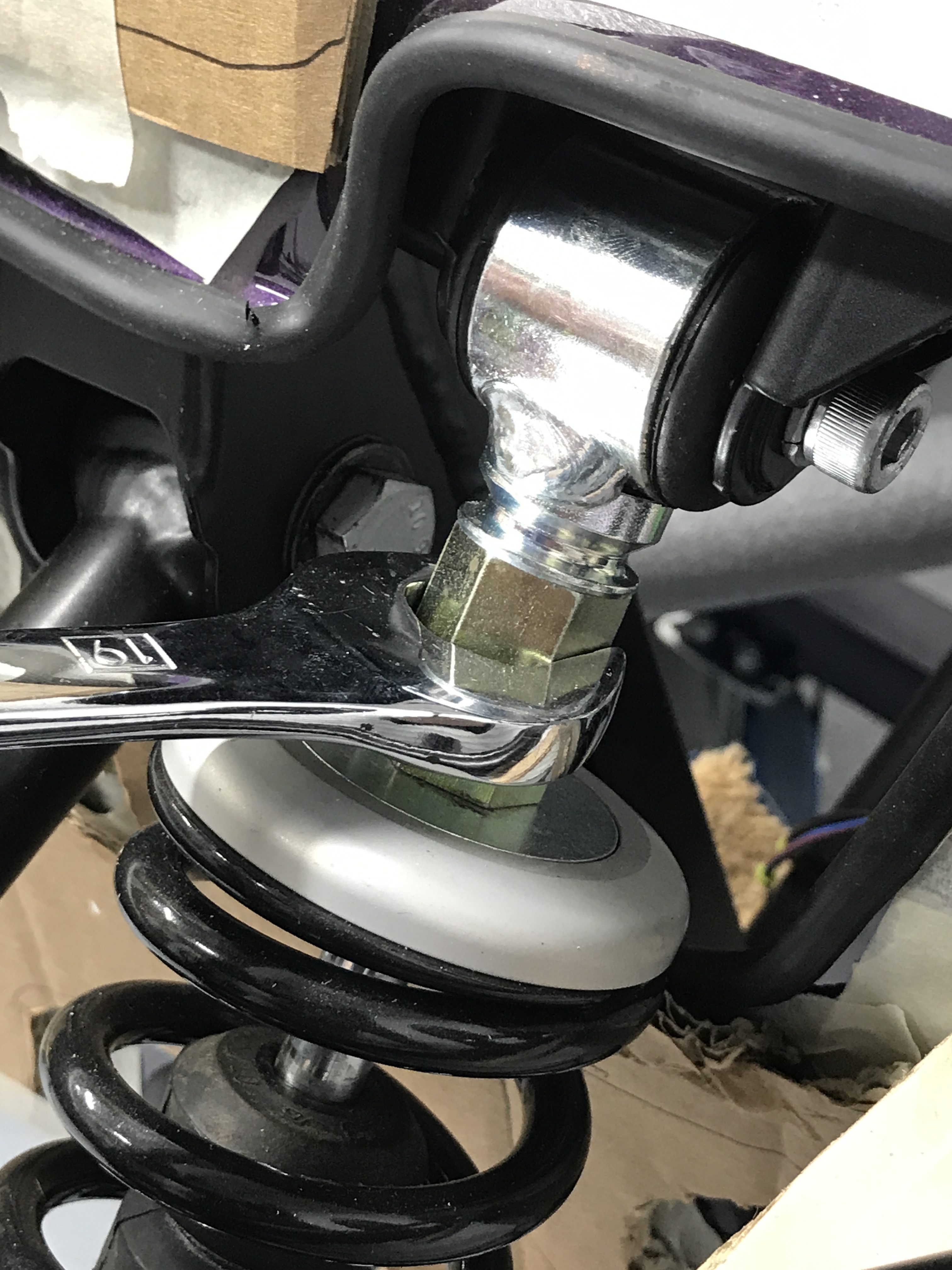
I also found that because the caphead bolt goes in at an angle it can be tricky to feed it through the spacer that’s now in the top of the damper. I found that a 19mm spanner on the top of the damper could be used to manipulate the damper and wiggle it until the bolt could be fed through.
Front Uprights
The off-side (O/S) upright went on with no particular drama. The only tricky bit was getting my socket set onto the upper upright nyloc nut. A wobble bar was needed but it was a bit of a fiddle to get it onto the nut.
The bottom nut was also a bit tricky because of the angle of the special nut going into the recess of the upright.
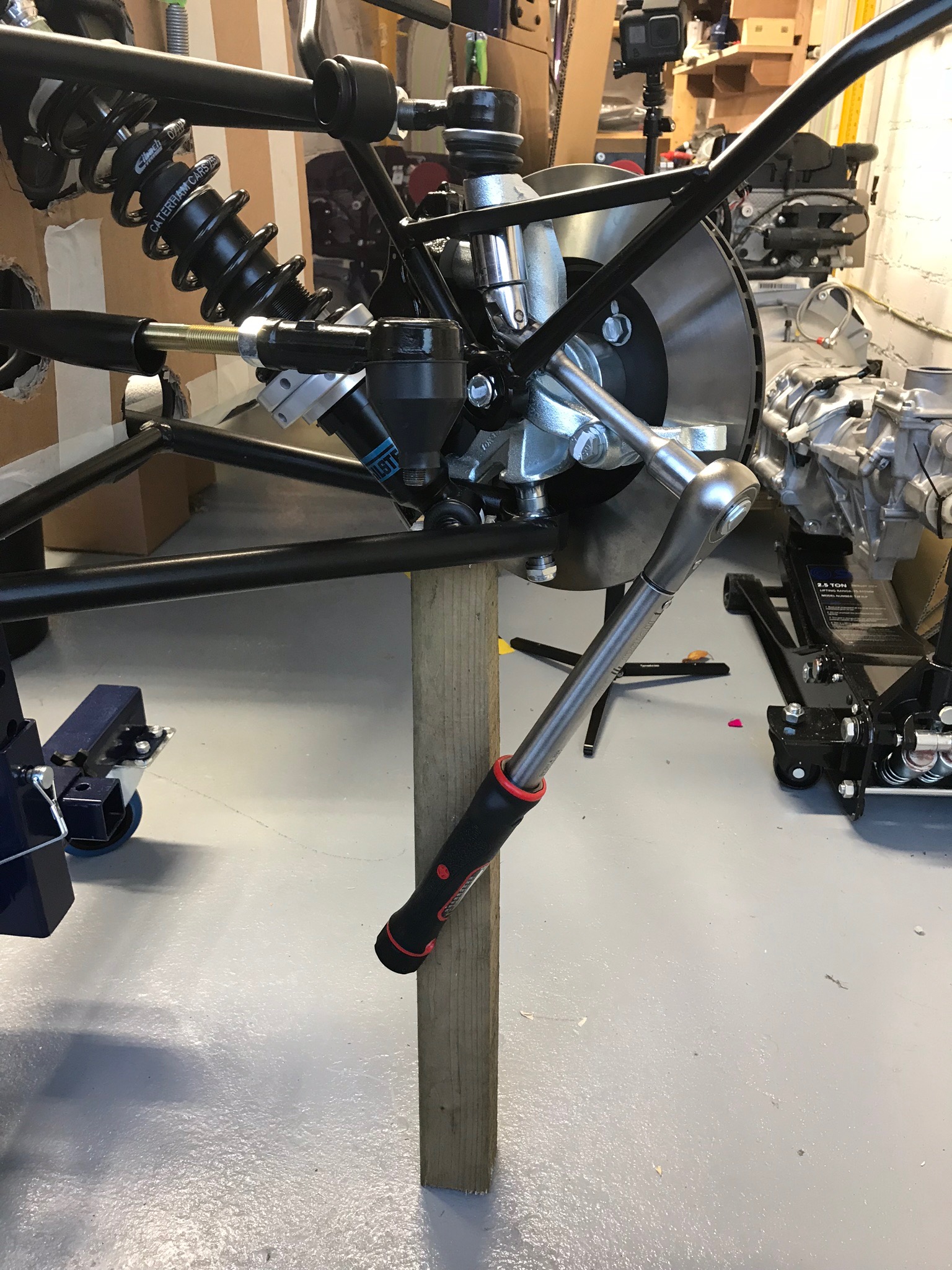
Because the front suspension is unsupported without the car being on the ground, the suspension sags. This puts the lower-wishbone-to-upright angle off from 90 degrees and pinches the socket you’re using to tighten the lower special nut – because of that limited gap on the left hand side talked about in the picture caption. My solution was to make a prop for the suspension unit and to therefore lift the unit to make the angle more like 90 degrees.
Since doing this part of the build I’ve re-read some other blogs and one proposed solution is to put the lower upright joint into it’s recess first. That way you can set the angle of the upright to the lower wishbone and the socket is able to get better access to the special nut. Hmmm. I get that that is an option but I was struggling with supporting the upright without having both the top and bottom nuts at least temporarily holding it all in place. I think its also advisable to have both top and bottom joints in place before torquing them up. You then get the problem of the bottom nut being pinched. I liked my prop solution, so happy with that.
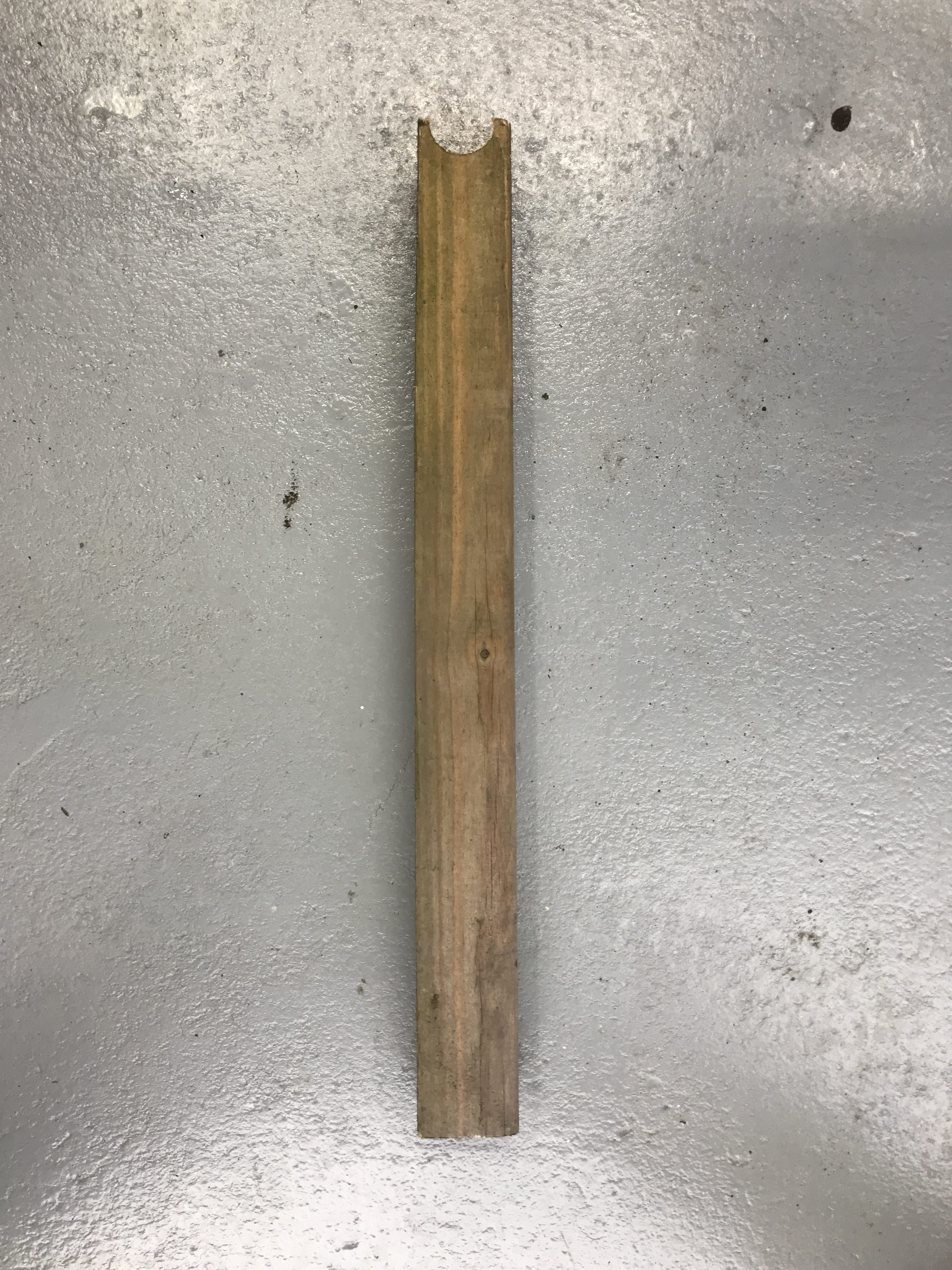
To make the prop I took an offcut of wood, drilled a 32mm hole in one end, then cut off that end through the centre of the hole. This made a cutout in the end of the wood that I could then sit safely underneath a wishbone bush joint. This set the upright to wishbone angle closer to 90 degrees and stopped the socket on the special nut from getting pinched.
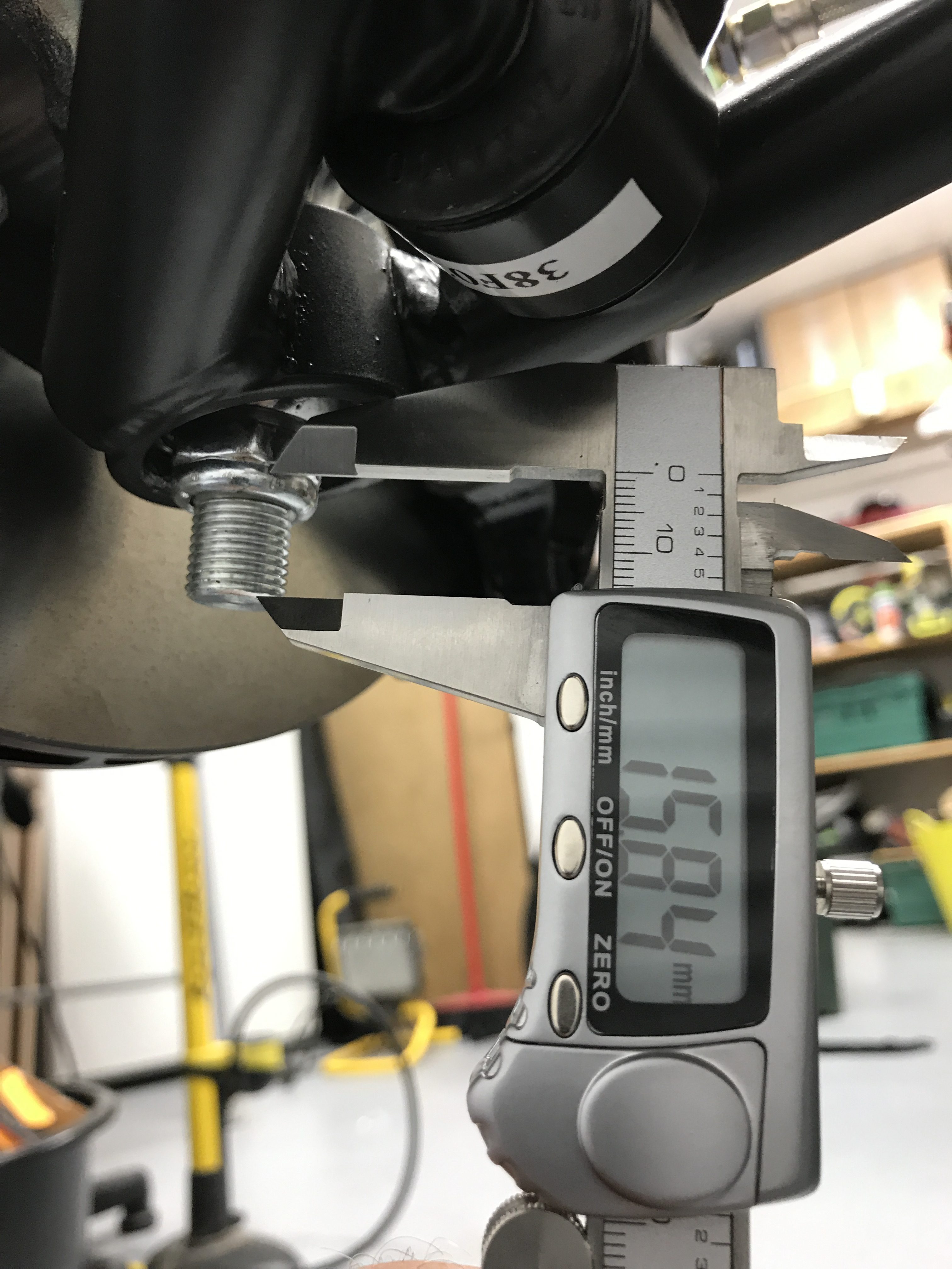
On another note, some bloggers have commented that they needed longer sockets to be able to tighten up the lower upright “special” nut. I didn’t find that with my socket set. The socket set I had was fine to do the nut up all the way and have enough socket on the nut to feel confident that it was “on” ok. My 19mm socket has 19.5mm of hex depth and 24.5mm total depth until it gets to the 1/2″ wrench shaft. As you can see from the picture with the callipers and the lower special nut, there’s about 16mm of depth required from the bottom of the thread to the hex part of the special nut.
Then near-side (N/S) went on with no drama and the use of my Heath Robinson prop. I could then attach the track rod ends to the uprights and torque them up. Or so I thought…
Track Rod Ends Again
I then stood back to survey the progress and realised that the two uprights were pointing in different directions – considerably different. They were both pointing outwards by probably 5 degrees. Hmmm… what had I done wrong?
It took only a few seconds to realise that I must not have got the track rod ends on far enough. A quick review of the build manual and I realised our mistake. As Harry and I were reviewing the manual we had clearly read the section on the track rod end locking nut too quickly. We thought it told us to put the locking nut on 13 turns but after re-reading it I realised it was the track rod end that needed to go on by that amount. Doh!
Easy remedy, remove the nyloc nut off the bottom of the track rod ends, wind the track rod ends on the requisite 13 turns and re-apply and torque the track rod end nyloc nut. That’s better. They’re close enough but will need to be set up properly along with the camber angle on the upper wishbone on a tracking jig during PBC.

I torqued and then paint-penned the nuts and bolts but wasn’t happy with how visible the markings are. I was using a white paint pen. It worked fine on some sections but almost invisible on others. So, I ordered a couple of different coloured paint pens to see if it would make a difference. We’ll see what happens when they arrive in the next couple of days.

Leave a Comment