

We were heading out on a family trip this weekend so I had just a couple of hours in the morning this morning to look at two jobs that I’d hoped to finish earlier in the week.
But first, the Washer Bottle. I’d not been able to sleep last night and so was pottering around the garage looking at where to locate the washer bottle. According to the build sequence in the manual, you need to get the washer bottle in before the engine gets installed because there isn’t enough room to fit it after the engine goes inl. But that’s what the build manual says, and of course things aren’t as simple as to follow the instructions. At the moment these diversions are fun – they haven’t resulted in anything going wrong and it hasn’t caused any delay. So… all part of the experience 🙂
There’s an explanation of the Washer Bottle story in the Email 4 : Washer Bottle in the Boot post.
Once the regular day had started I wanted to get two jobs done: The Front Anti Roll Bar and the Horns.
Front Anti Roll Bar
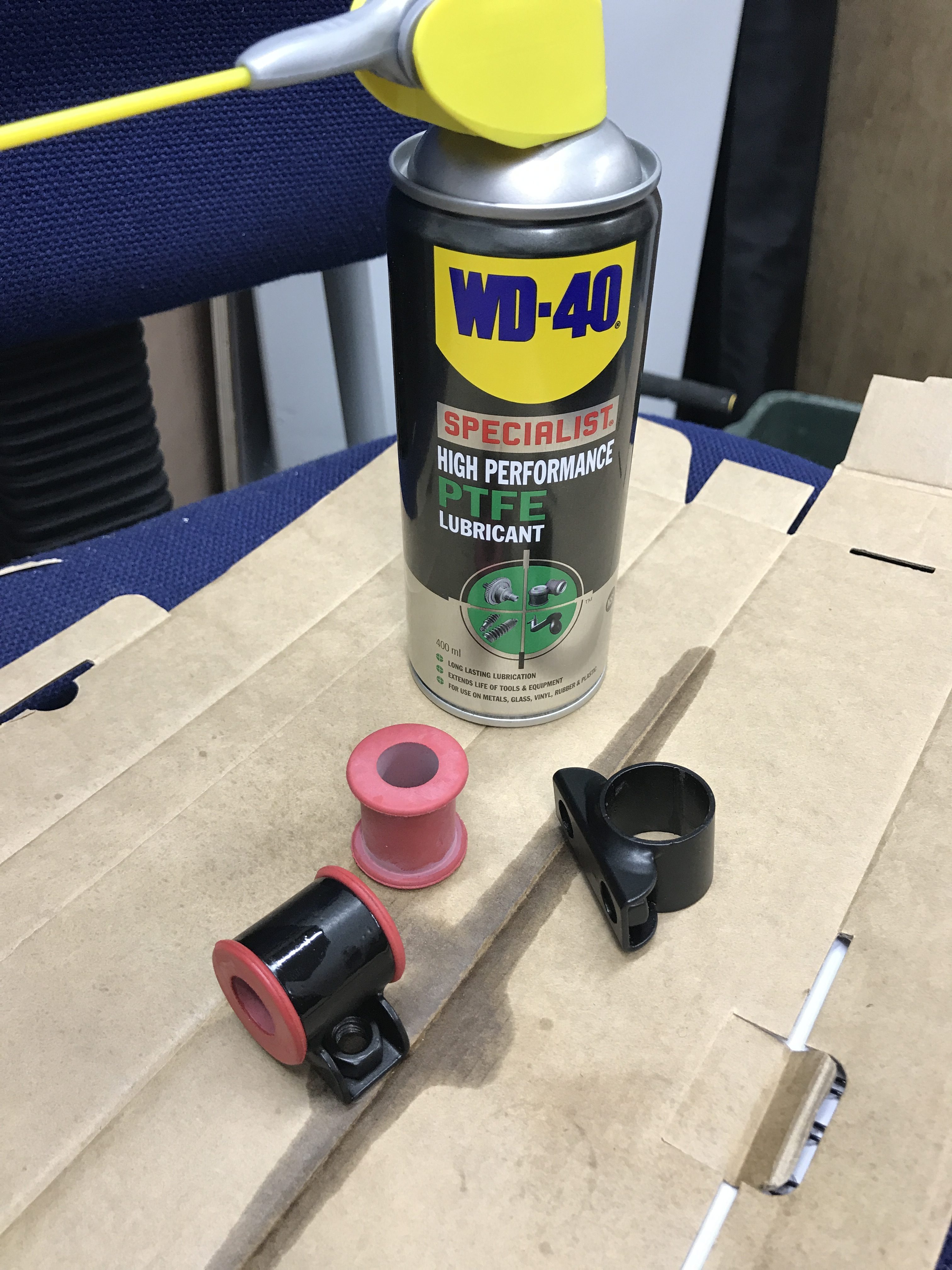
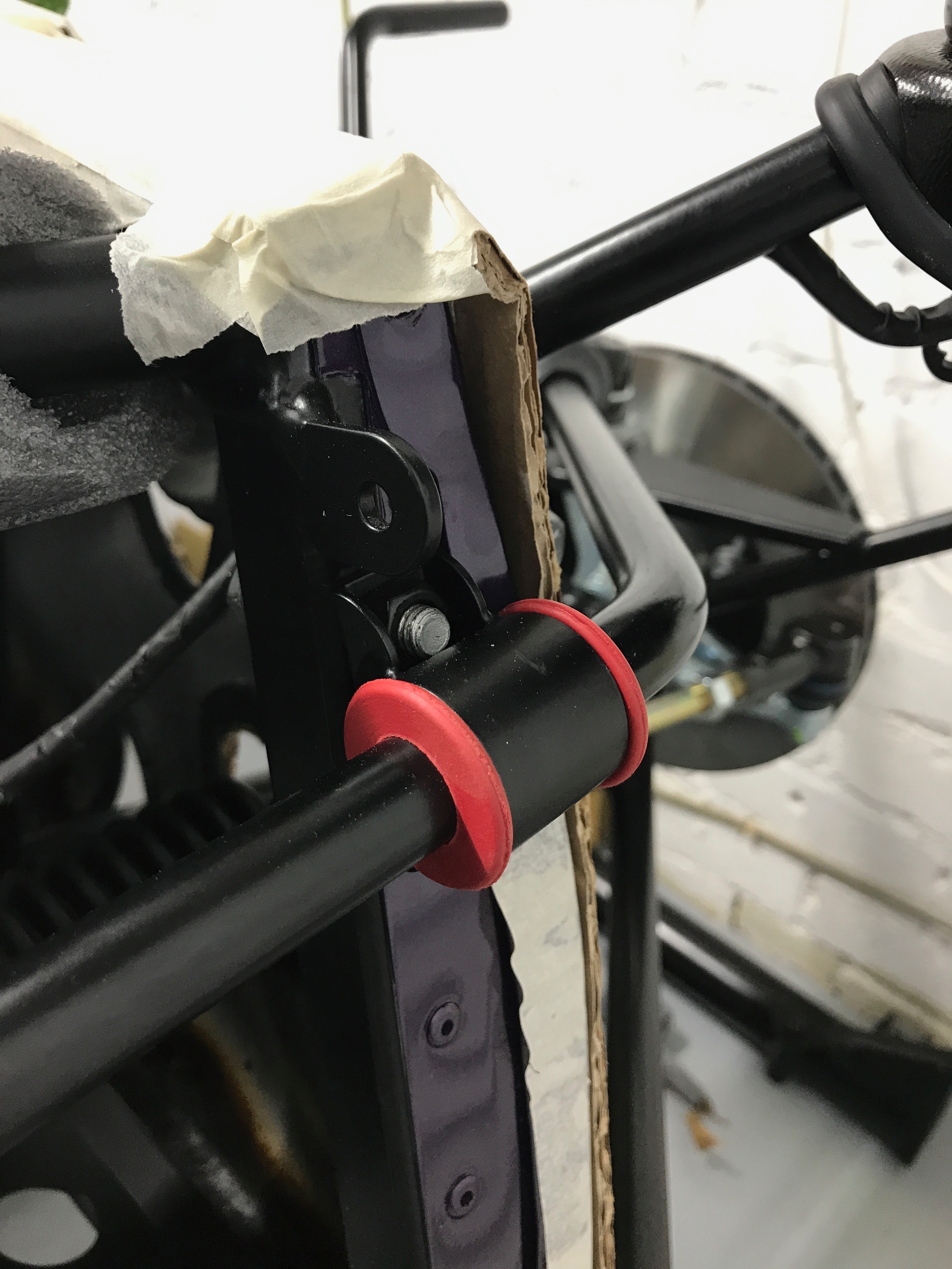
The front ARB connects the two upper wishbones together with a (nominal) 15.5 mm bar, shaped vaguely in a U shape. The front ARB I have seems to be slightly oval – it’s ~15mm in the vertical dimension and ~16mm in the horizontal. There are threaded sections on each end that take plastic balls that fit into sockets on the upper wishbones. The middle section of the ARB is held in by two “rubber” bushes that fix the ARB to the front of the chassis via circular clamps.
I’ve discussed the conundrum I’d had regarding what colour bushes to use for the ARB (it’s the red ones for the front ARB) in a previous post, Email Derek 2 : ARB Bush Colour and the Red Dot.
With the red bushes in hand and a reasonably generous coating of rubber lubricant (WD-40 PTFE) the bushes slipped into the clamps easily…
.. and then onto the ARB, also, with relative ease. They need a bit of a shove to get them around the approx. 45 degree-ish corners on the ARB but essentially no problem.
Once you have the bushes and clamps on the ARB you can add the boots that ultimately cover the joints to the upper wishbones and then screw on the ball ends with Locktight applied.
Where the problems did start were with the balls on the end of the ARB and getting them into their upper wishbone sockets.
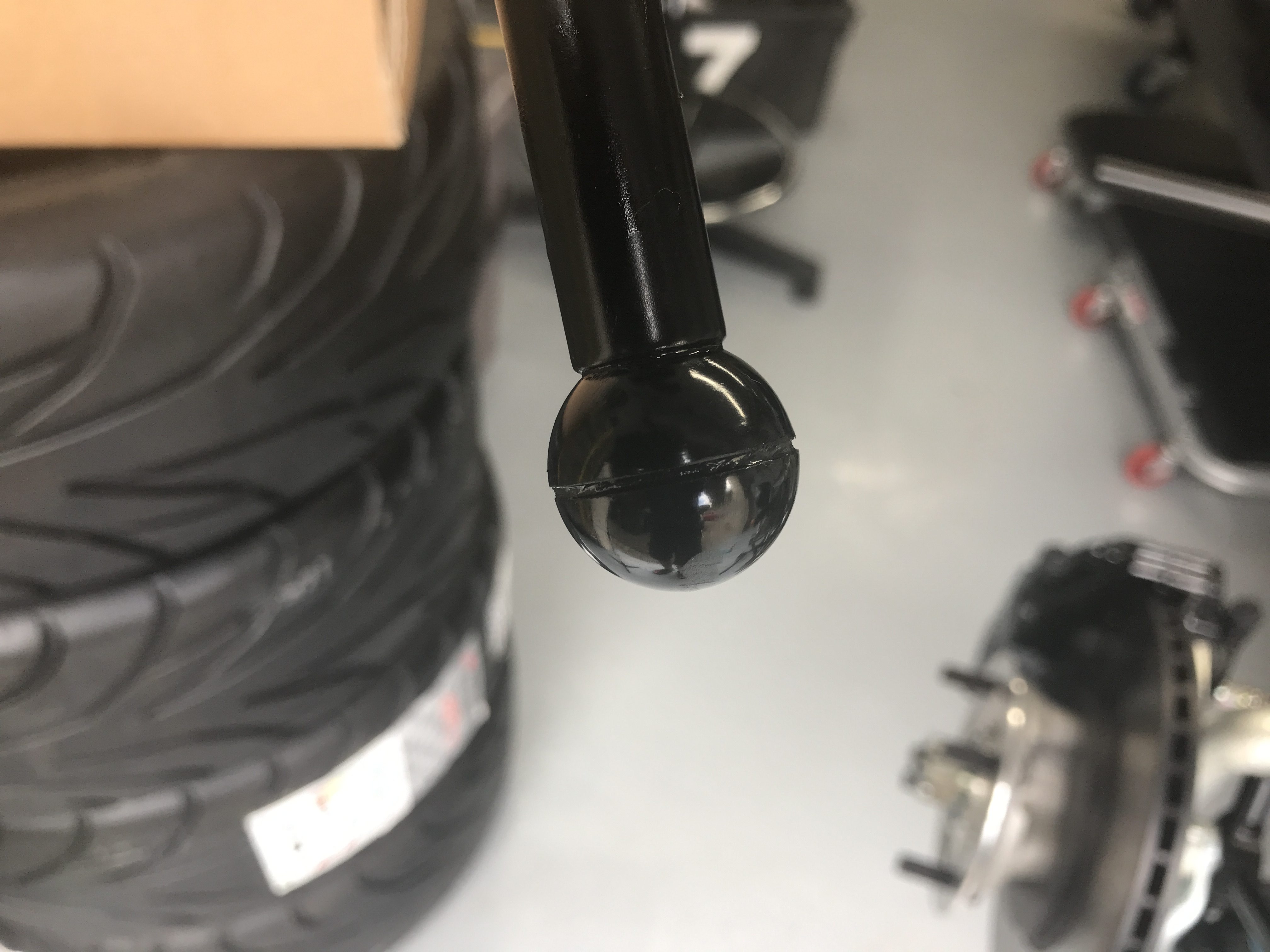
I applied Locktight to the threads of the ARB and screwed on the ball ends. I greased the sockets and the balls. The ARB was then offered up to the wishbone sockets but the balls essentially just sat on the perimeter of the socket and didn’t drop into them as I thought they should.
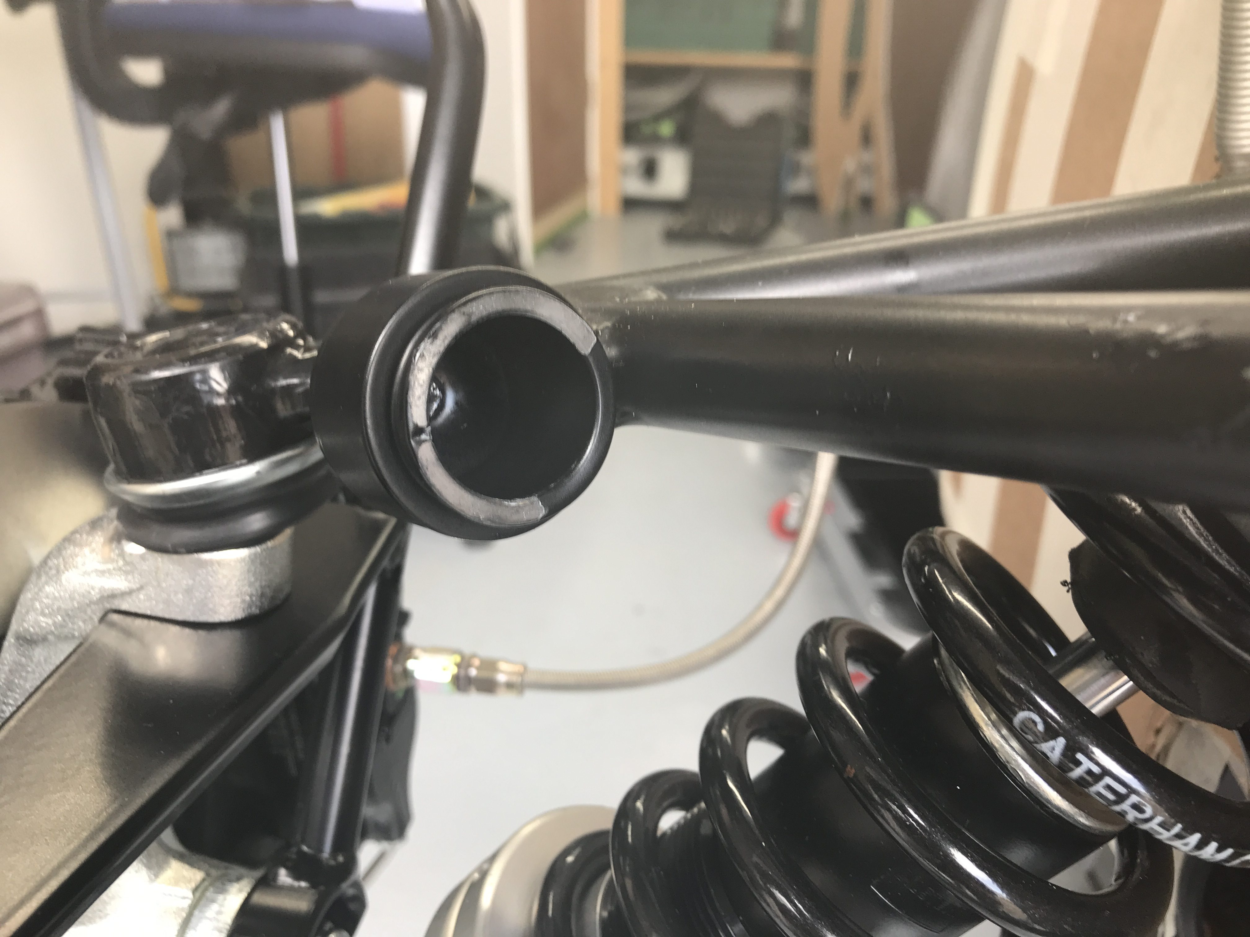
A quick google and it seems others had similar problems, but, as I expected the ARB should sit in the sockets not on them. Some suggested that you need to clear the sockets of some powder coat and that should do the trick. There were also suggestions that you can get a hydraulic seal if you use too much grease, but it didn’t feel like that sort of a problem…. it was a mechanical block that was stopping the ball entering the socket.
I also noticed that the balls on the end of the ARB were not moulded perfectly round. They looked to be a two part mould and the two hemispheres didn’t quite line up.
So, out with the dremel and the dremel flexible drive and I ran around the insides of the wishbone sockets. While I was at it I also trimmed some of the excess off the non-aligned hemispheres to see if that would help too.
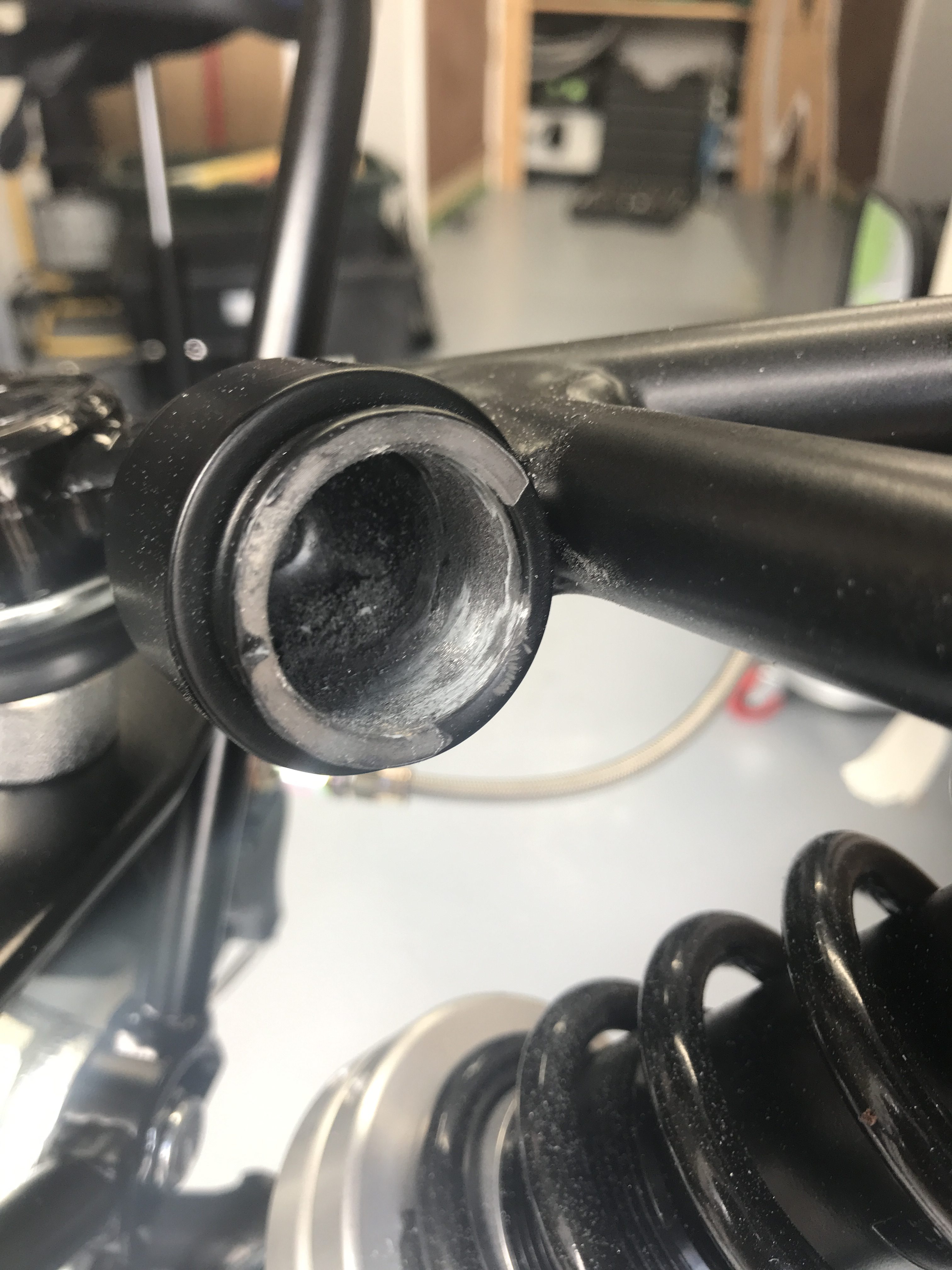
Other’s had commented, and I agree, that there’s not much threat of corrosion on the upper wishbones after the power coat is removed… because the ARB ends are covered with a boot that encloses the open end of the wishbone socket and the ARB ball.
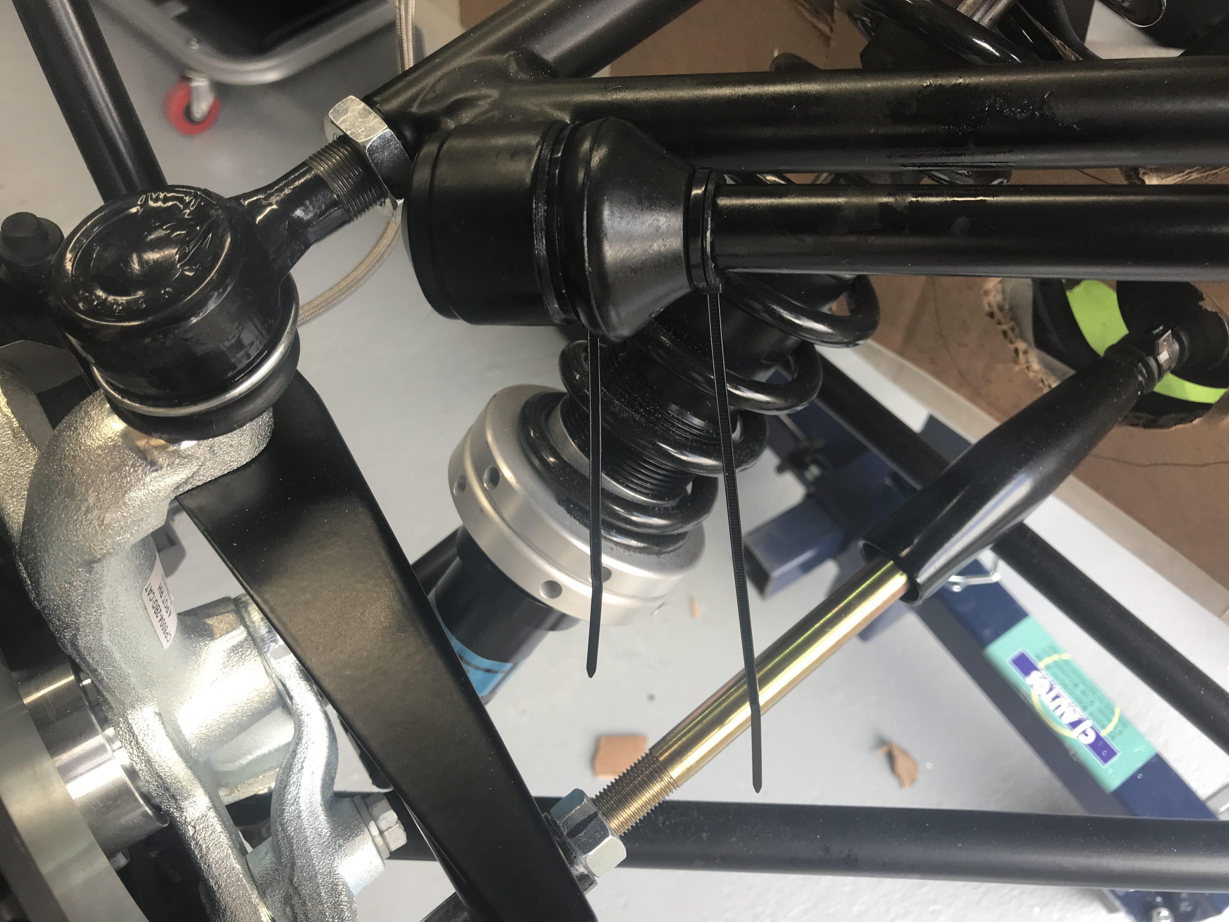
Once I’d fettled the sockets and the plastic balls, the ARB dropped into the sockets with no problem. In fact they might have been a little bit loose. I came to the conclusion that this probably wouldn’t be a problem seeing as the whole thing was under quite a lot of tension. Even though the balls dropped in with no resistance the whole ARB needed to be put under tension to get it fitted. So the ARB ball ends sat in the sockets tightly. As the ARB does its job the balls and bushes need to be free to move. I think that’s exactly how I think I’ve left it.
Last job here was to attach the clamps that surround the bushes to the front of the chassis and to torque them up. Simple job took a couple of minutes.
In all the front ARB probably took 45 minutes to get attached.
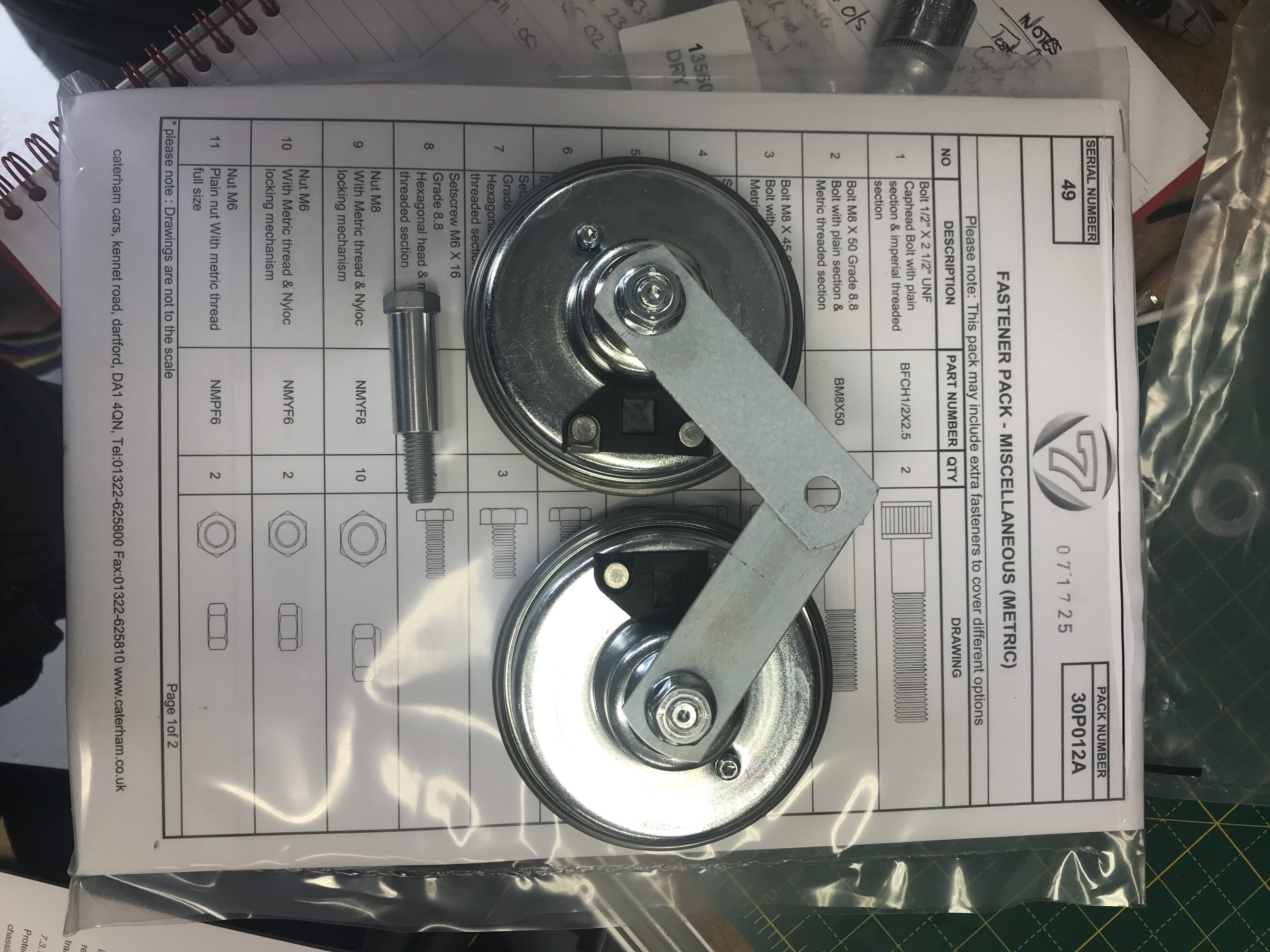
Horns
On the 420R the horns have to sit in a different position than normal. You have to drill a hole in the steering rack cross member and mount them below it. It’s also recommended that you undo the nuts holding the horn to its bracket and rotate the brackets. This is so that the horn electrical connections are close enough together to get the wire from the electrical loom onto them.
The first job was therefore to undo the nut holding to horn to its bracket. Others have recommended a breaker bar be used because the bracket nuts are quite tightly screwed onto the horn. My solution was to use a vice – simples.
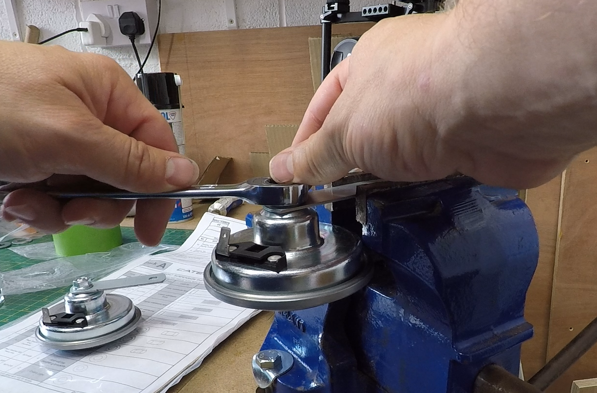
The horn brackets can then be rotated to bring the electrical terminals closer together.
It was then a case of drilling an 8mm hole in the steering rack cross member and attaching the two horns with the an M8 bolt, spacer and spring washer.
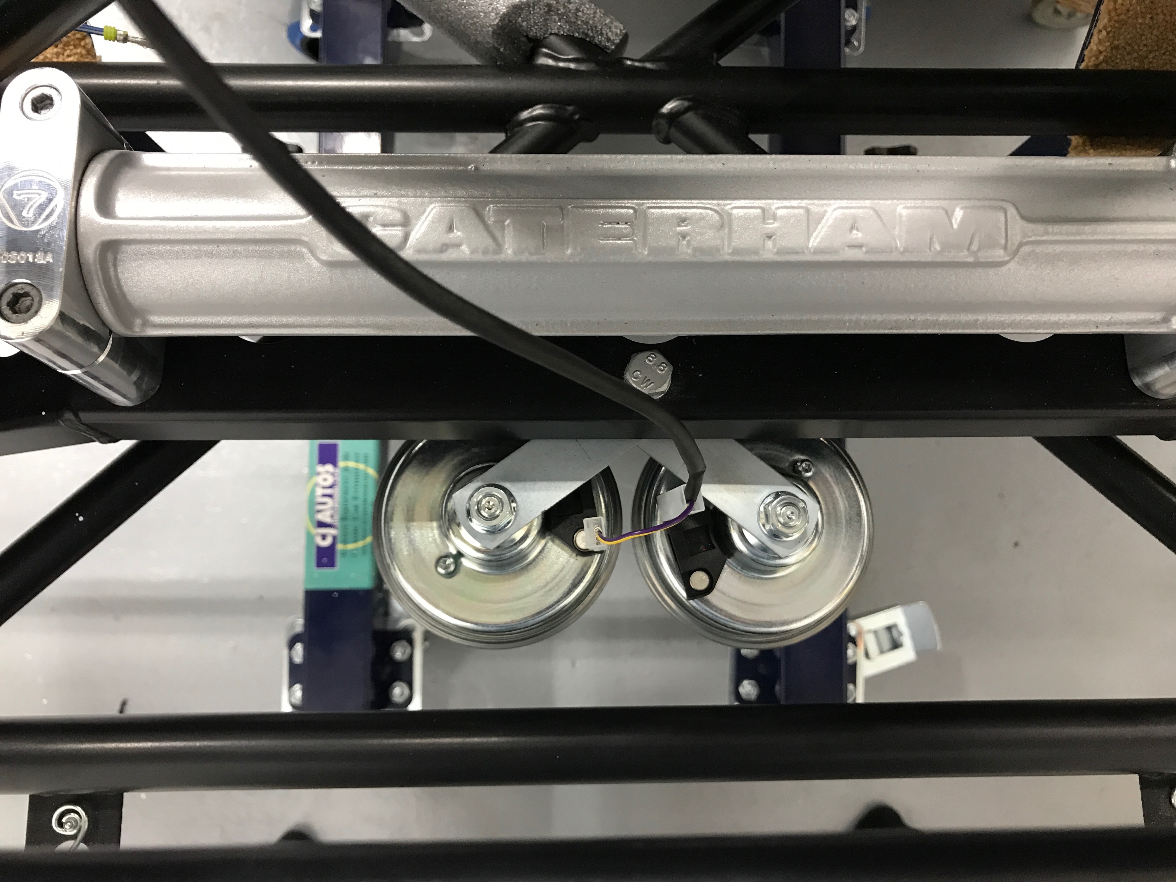
There seemed to be a couple of options for fitting the wiring to the horns. There are two sets of wires with two spade connectors that seemingly could be used: one with a single wire that’s looped from one connector to the other and a second set of wires that have what look to be separate feeds coming to the two connectors. It clearly had to be the single-looped set of wires – one of which is yellow/purple.
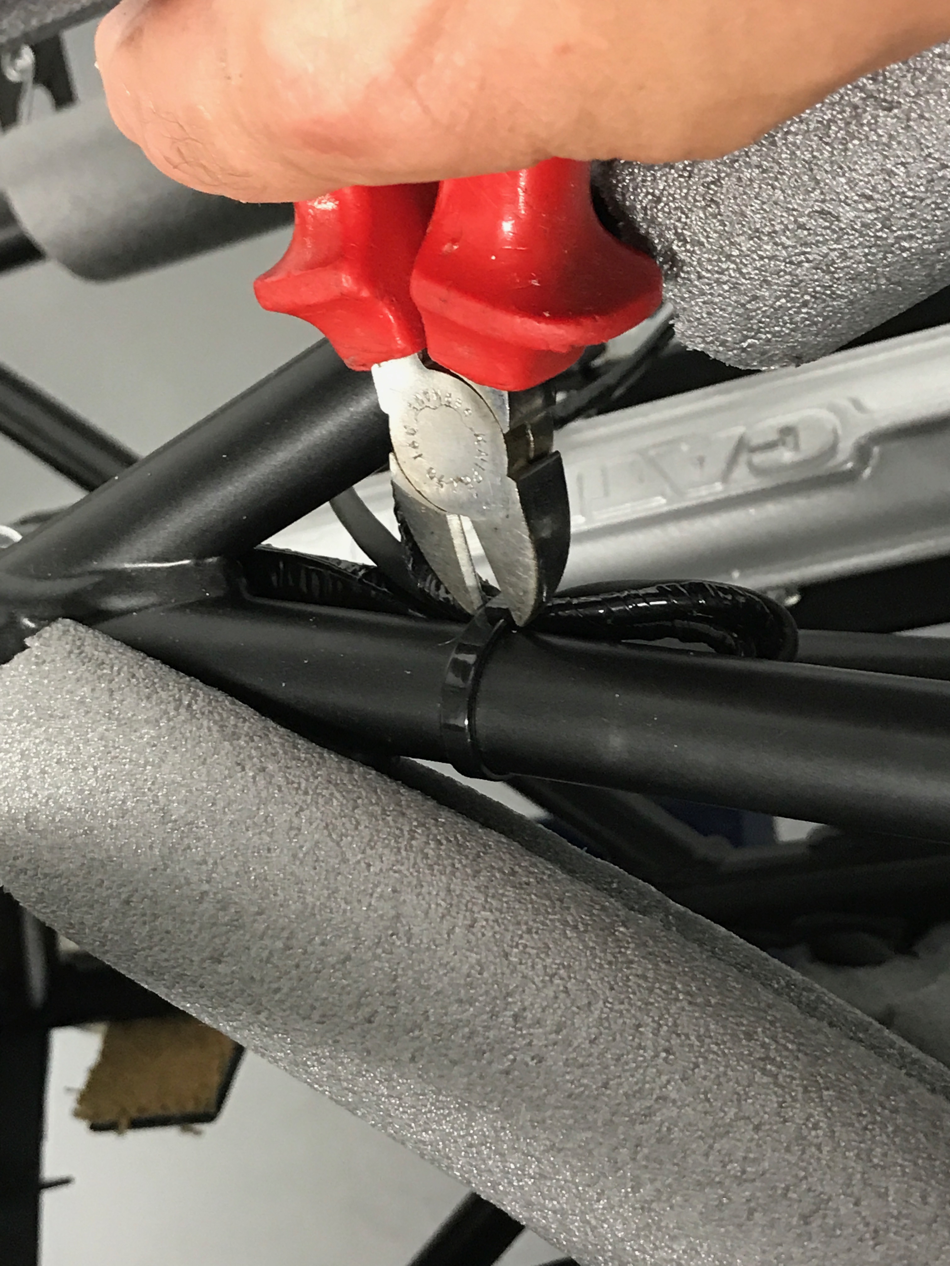
However, those wires don’t reach from the loom to the spade connectors on the horns – they’re not long enough on my loom because there’s a cable tie used to hold these wires to the chassis as the wires double back for strain relief. I decided to snip the cable tie that holds all these wires, and the loom, to the upper chassis rail. If I removed the cable tie then the purple/yellow cable would reach. It seemed sensible to re-attach a cable tie to the remaining wires so they were secure and the job was done.
That was the two jobs completed for the day. Off to see the family and then thinking about doing the engine install on Monday (August bank holiday Monday – a public holiday in the UK).

Leave a Comment