
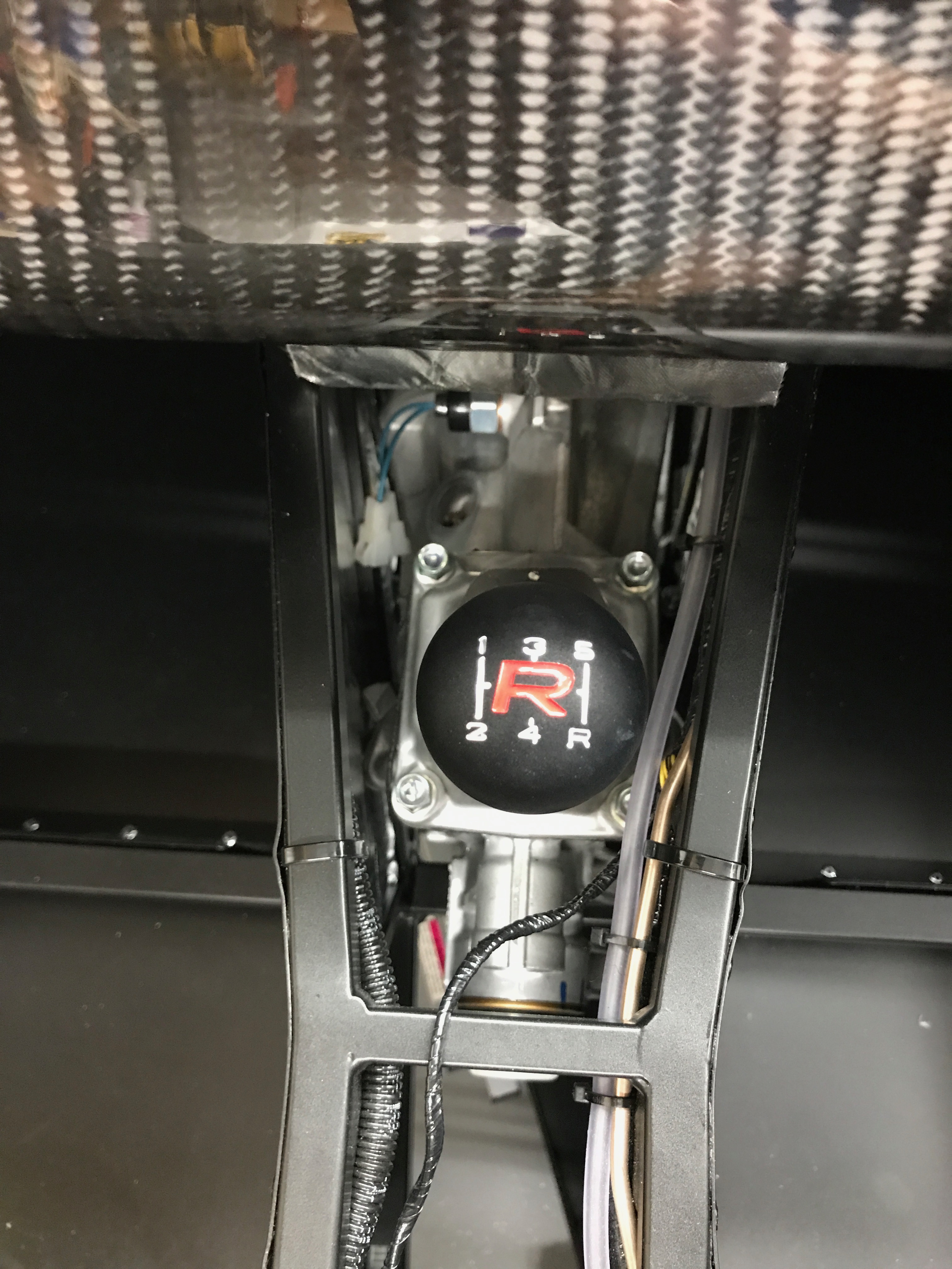
Saturday morning and a chance to get a few hours in on the car. I’d not really had a chance to do anything since putting the engine in last Monday. I had managed to sneak into the garage late one night and fitted the gearstick and gear knob, but that’s more of a treat than a task.

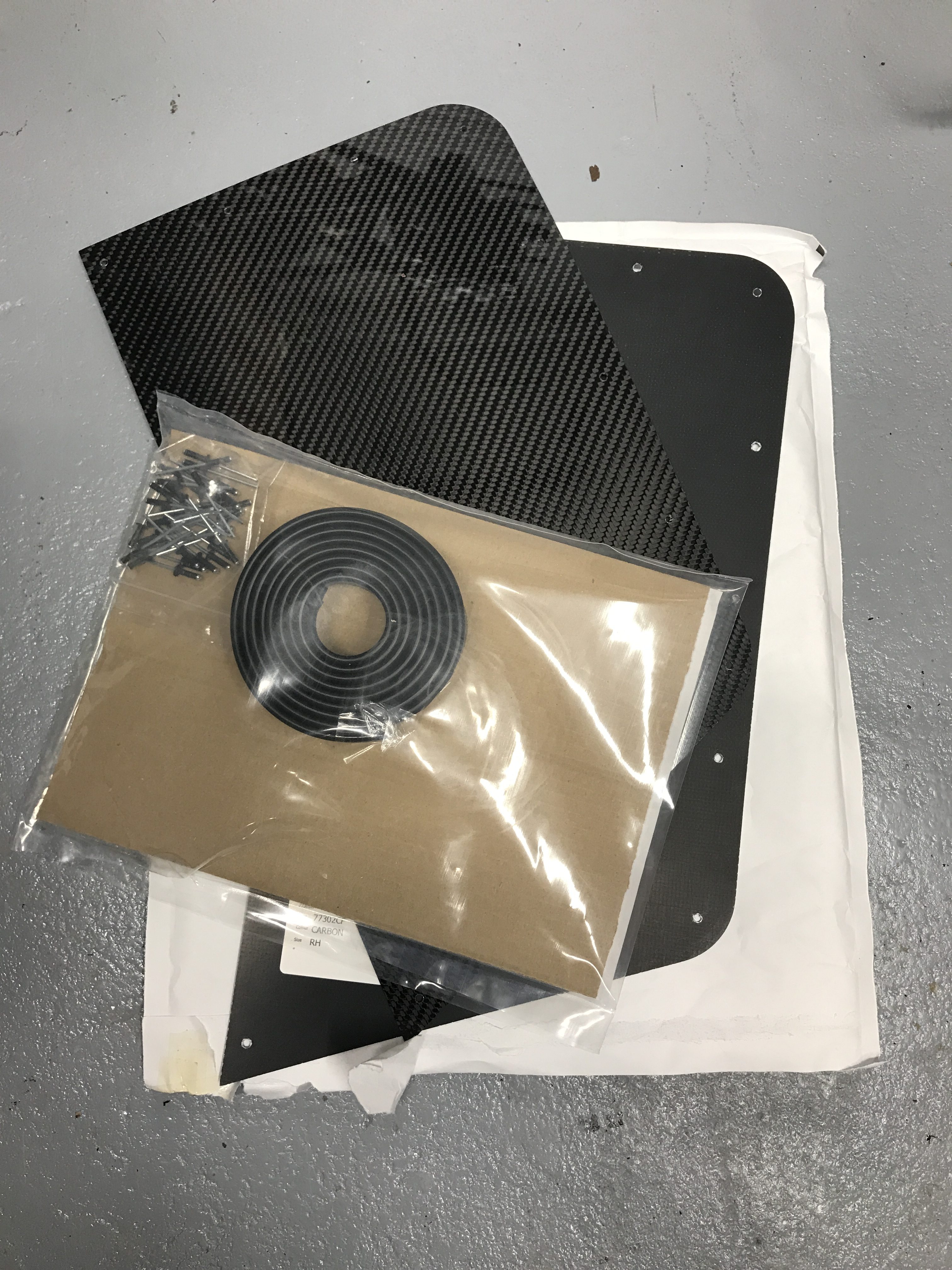
Wing Protectors Delivery
We also got a delivery during the week… I’d been rummaging through the various cardboard boxes that we now have left to empty and I couldn’t find the rear wing protectors. A quick email to Derek and the protectors arrived mid-week.
Engine and Gearbox Revisit
Back to Saturday though… Just as I got started I had a helper show up. A family friend had been keen to come and help and he showed up this morning to lend a hand – thanks Jack.
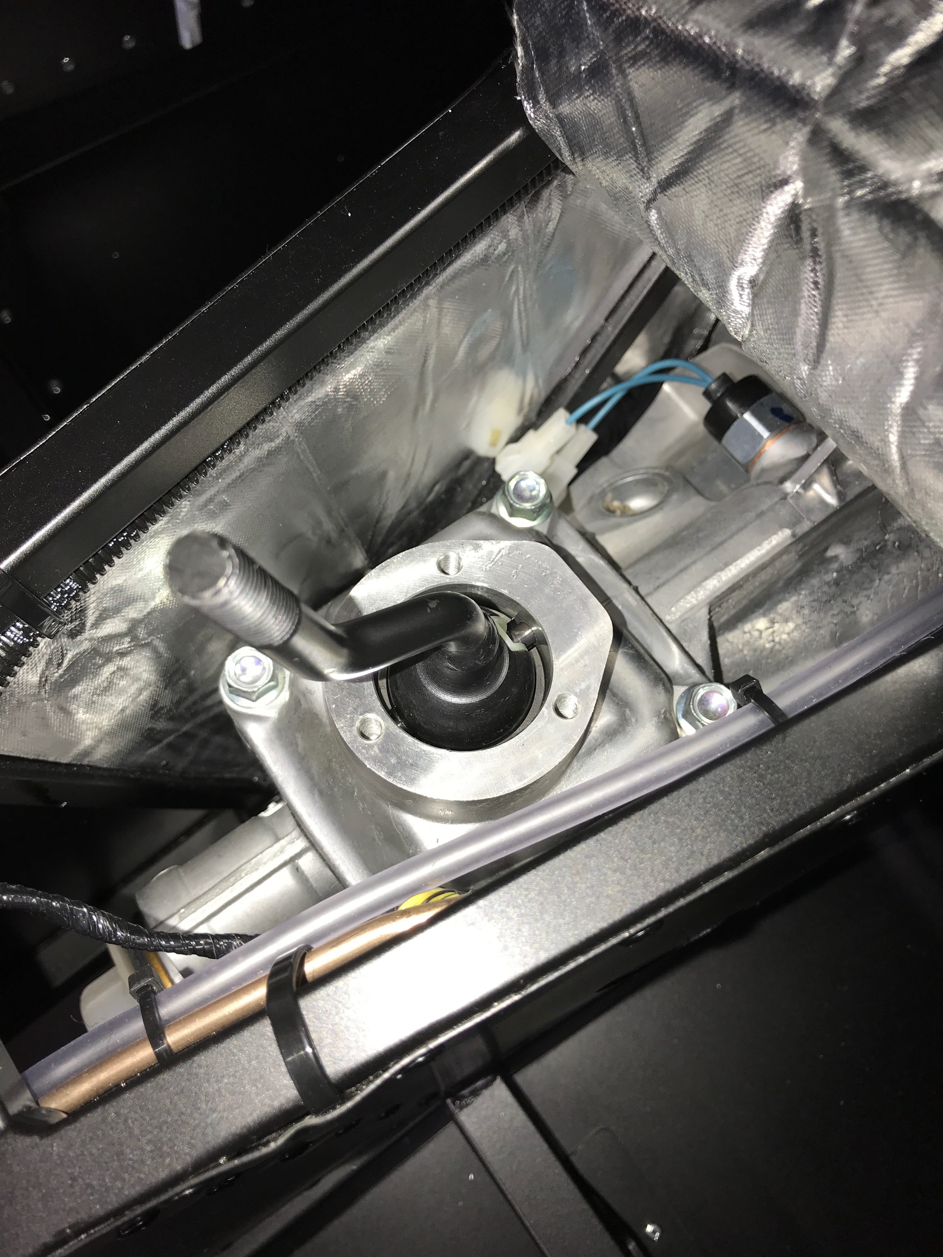
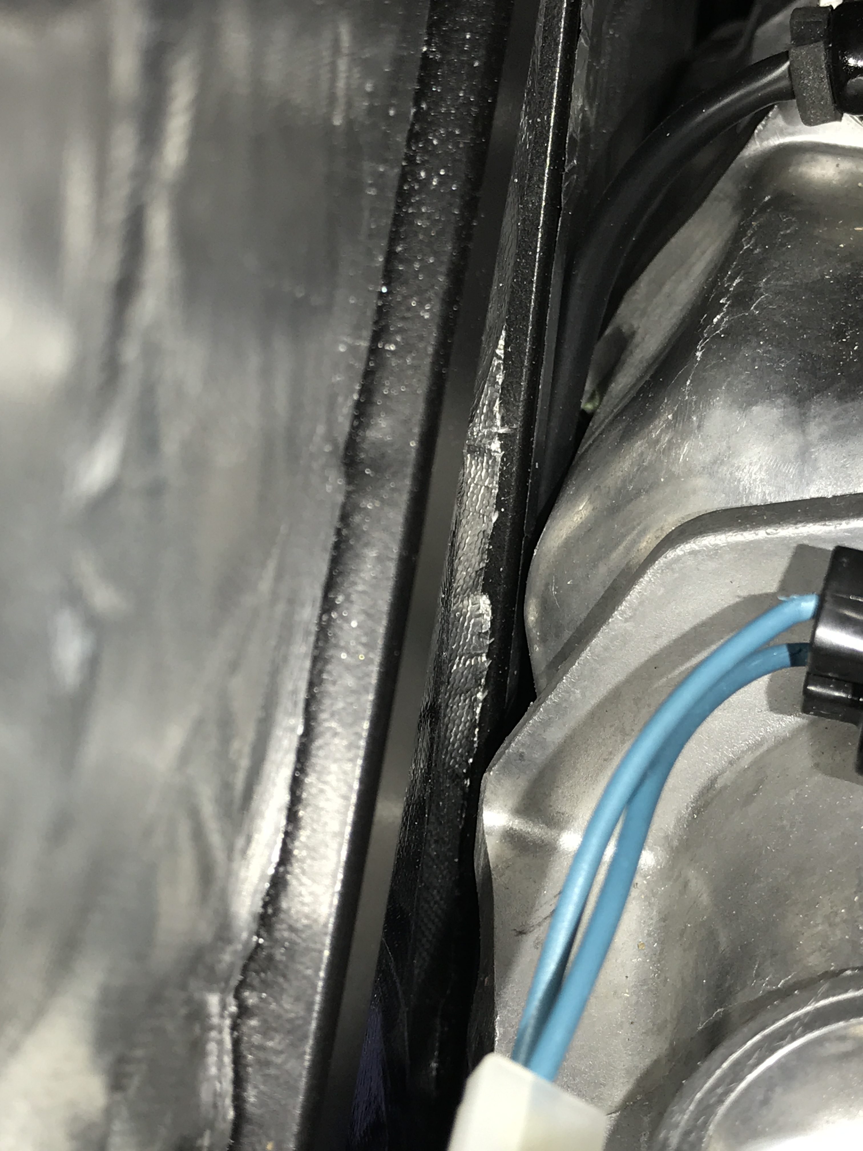
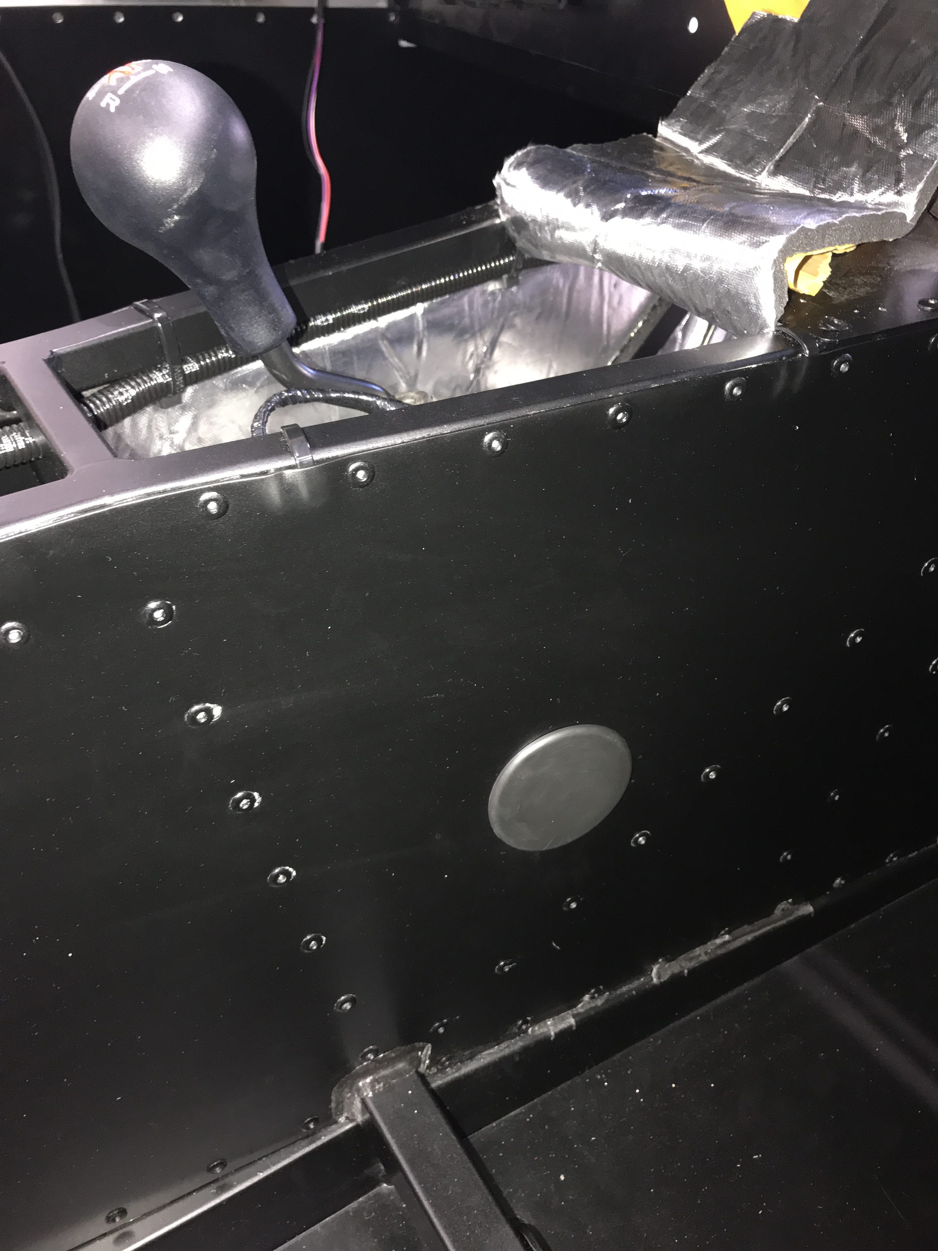
The closeness of the gearbox to the left hand side transmission tunnel wall had been bugging me. I had had a couple of goes at increasing the gap between LHS of transmission tunnel chassis and the gearbox but with not effect. Surely it couldn’t be as close as it had ended up with.
So… Jack and I got the jack out (sorry couldn’t refuse that one) to give it all a tweak. We lifted up the engine and gearbox again with our trolley jack and undid the gearbox and engine mounts. We then spent a good 45 minutes trying with screwdrivers and a crow-bar to see if we could move the gearbox over – no joy, again!
Whatever we did it resolutely stayed put. I tried “persuading” the engine mounts with a rubber mallet, crow-bars between gearbox and chassis and all sorts of jiggling of the jacks (both of them) and bolts.
The gap between gearbox and chassis remained the same at around 1mm.
This is going to have to stay like this until at least the PBC.
Later that day I had a visit form Lotus Pete, from two doors down. He had a look at the gap and pronounced: “it is a bit tight… but you’ll never move the engine over on any play in the mountings. It therefore shouldn’t move too much under cornering”. And.. subsequently in an email exchange with Derek Howlett he confirmed “they are all close”. That’s enough for me… we’ll see what Williams say.
Electrics
Jack and I then turned our attention to the engine and gearbox electrics…
The gearbox reversing switch was first. There’s a set of plugs located in the transmission tunnel that you have to connect to the reversing switch on the gearbox. There are actually two sets of connections on the gearbox, the front most are the reverse switch, the rearmost are a neutral selection switch (telling you when you’re in neutral) – not used on Caterhams.
It was a bit of a fiddle getting our fingers to the plugs down the transmission tunnel but Jack got there in the end.
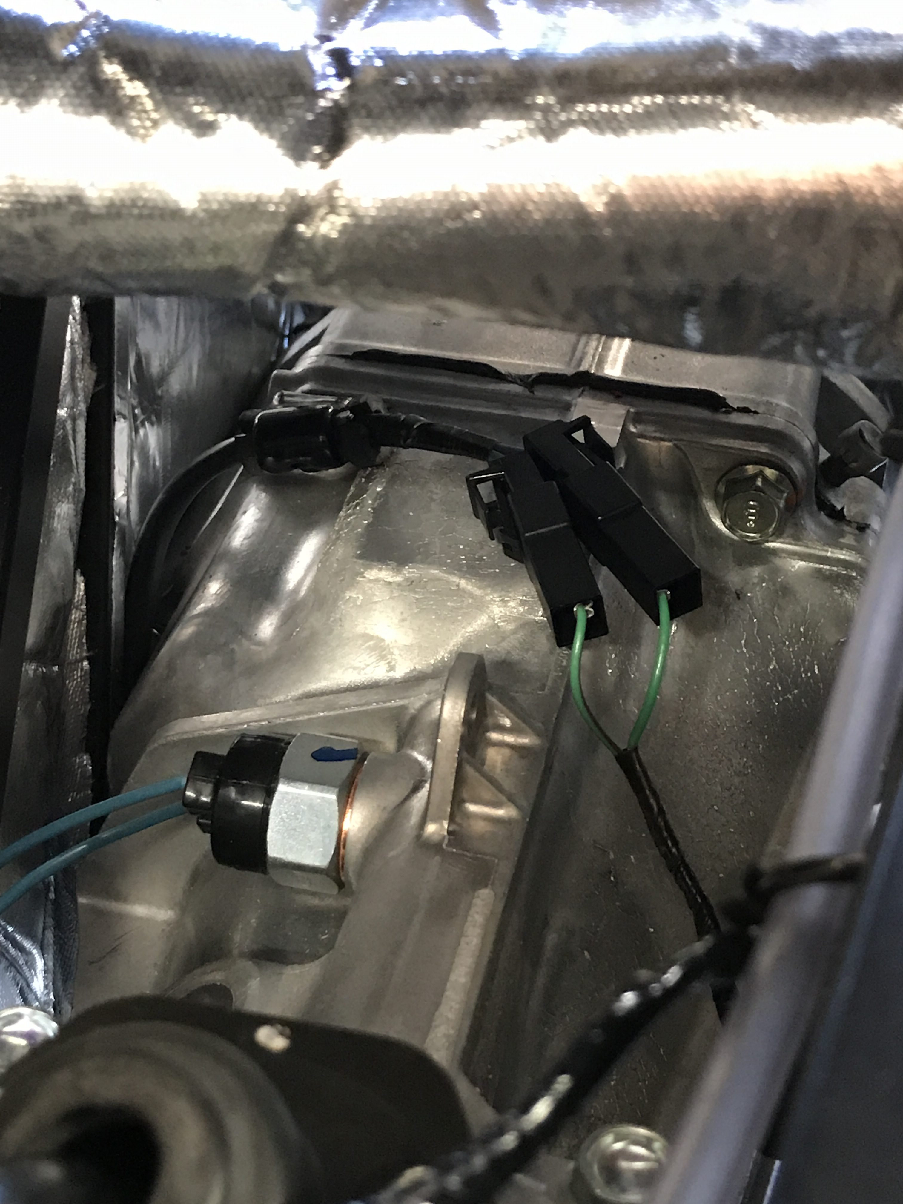
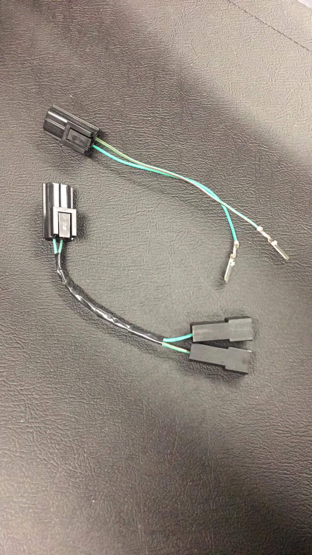
[ Since completing my build I’ve seen comments and talked to a couple of new builders that didn’t have the same connectors as I had for the reverse switch – it was a simple push fit for me. One builder just had to jam two spades, with no shroud, into the female side of the connection. As of 2018-07 is now seems that Caterham ship a stub lead in with the engine fittings to go from spade to bullet connections… The image below is from Will Baverstock’s 270R build…
There’s a grommet that needs fitting to the driver’s side footwell, and another one for the passenger side, but we didn’t fit this passenger side one at the moment in case we need to get to the gearbox filling plug – its conveniently set behind a hole in the passenger side transmission tunnel wall.
Next up is the main ECU-to-loom plug and socket. This is a large grey and red connector that sits forward and below the battery. The connection is simply made with a push and lever to retain the connection.
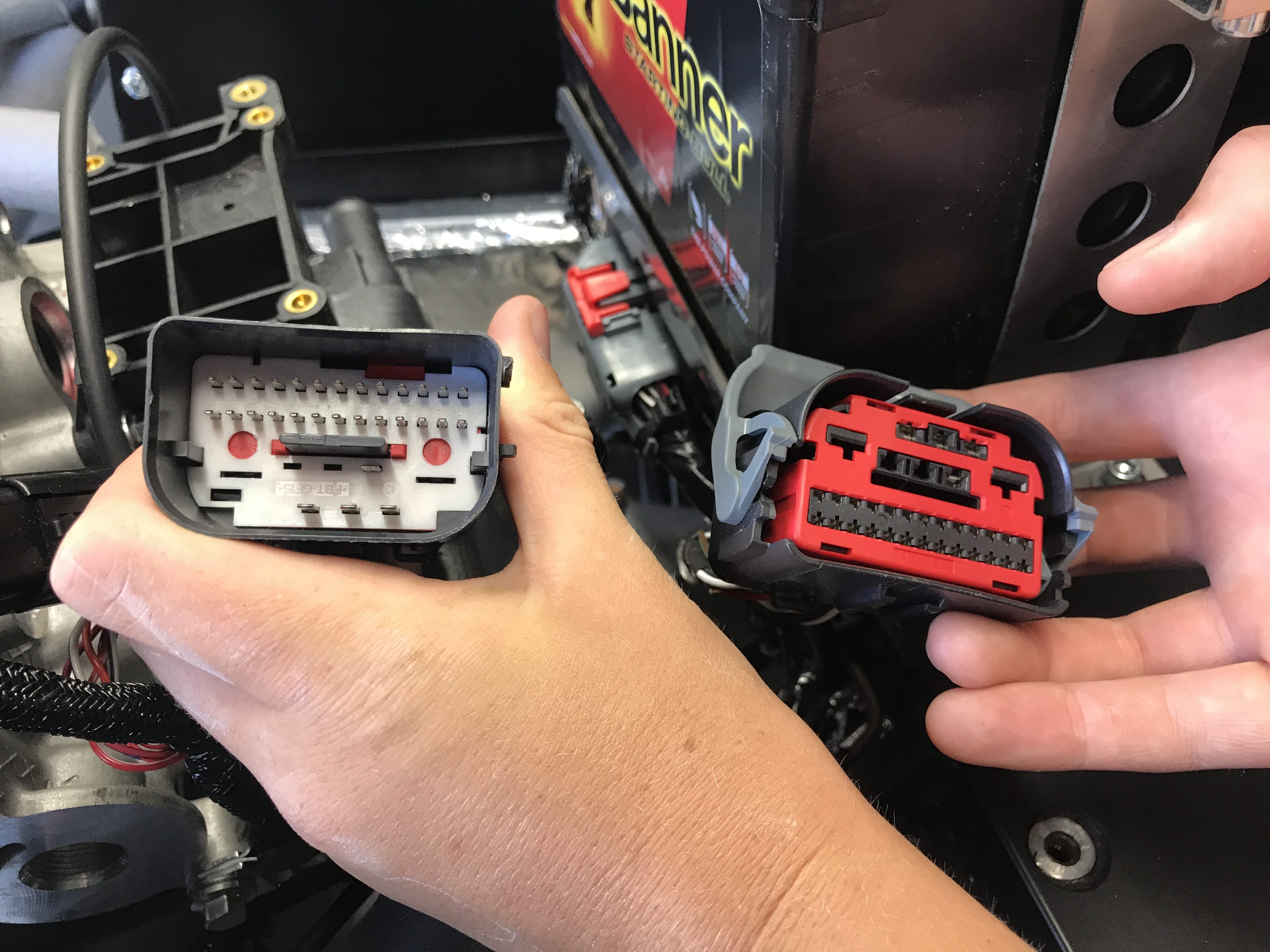
What’s not obvious is where this connector is going to be sited when done. I’ve seen various pictures of self-build and Catherham built Sevens and they all seem to have this connector floating down below the battery. It’s going to need to be cable tied to something to stop it rattling around but its not obvious how it should be orientated and what it should be tied to.
Power to the Starter Motor
Next we connected the main 12v lead to the starter motor. The manual tells you to connect the battery at this point but I wasn’t in need of any power to anywhere so decided to leave the battery disconnected. I was also unsure about where to locate the engine earth connections and wasn’t ready to connect them either so the battery was going to stay detached for the moment. More to come on earthing in a later post.
Back to the 12v connections… I ordered the car with the 12v cutoff switch.
I’d read lots of forum posts and blogs where people have had problems with laying cars up over winter and finding that they car’s battery was flat in the spring. I’m hoping not to lay the car up for too long but that’s just the plan, I can well see that my desire to drive in all weathers might wane after a few years/months/weeks (delete as appropriate).
Anyway, we have two cables as part of the cutoff switch, helpfully labelled as S (starter) and B (battery).
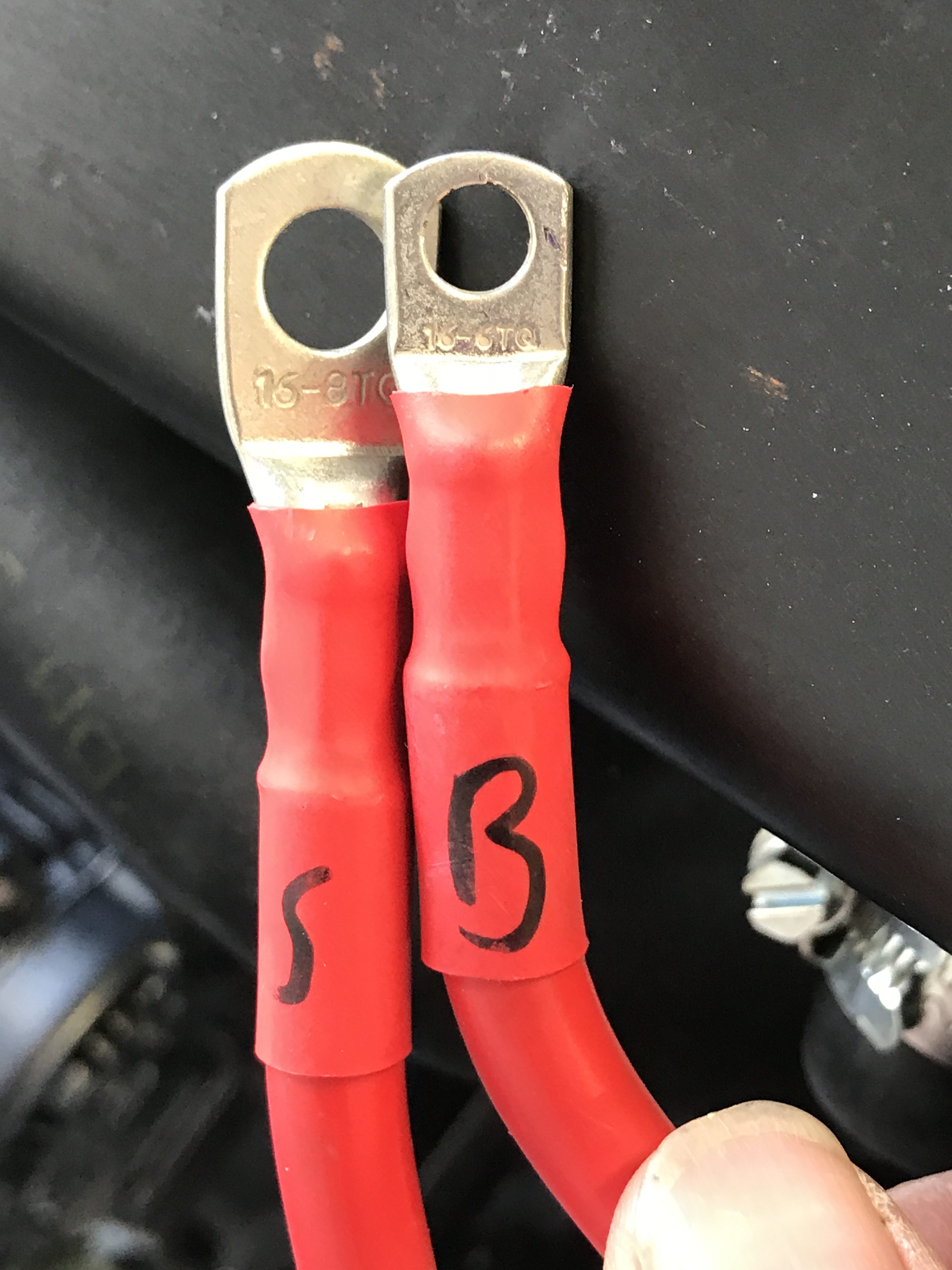
The S lead goes to the starter assembly as below…
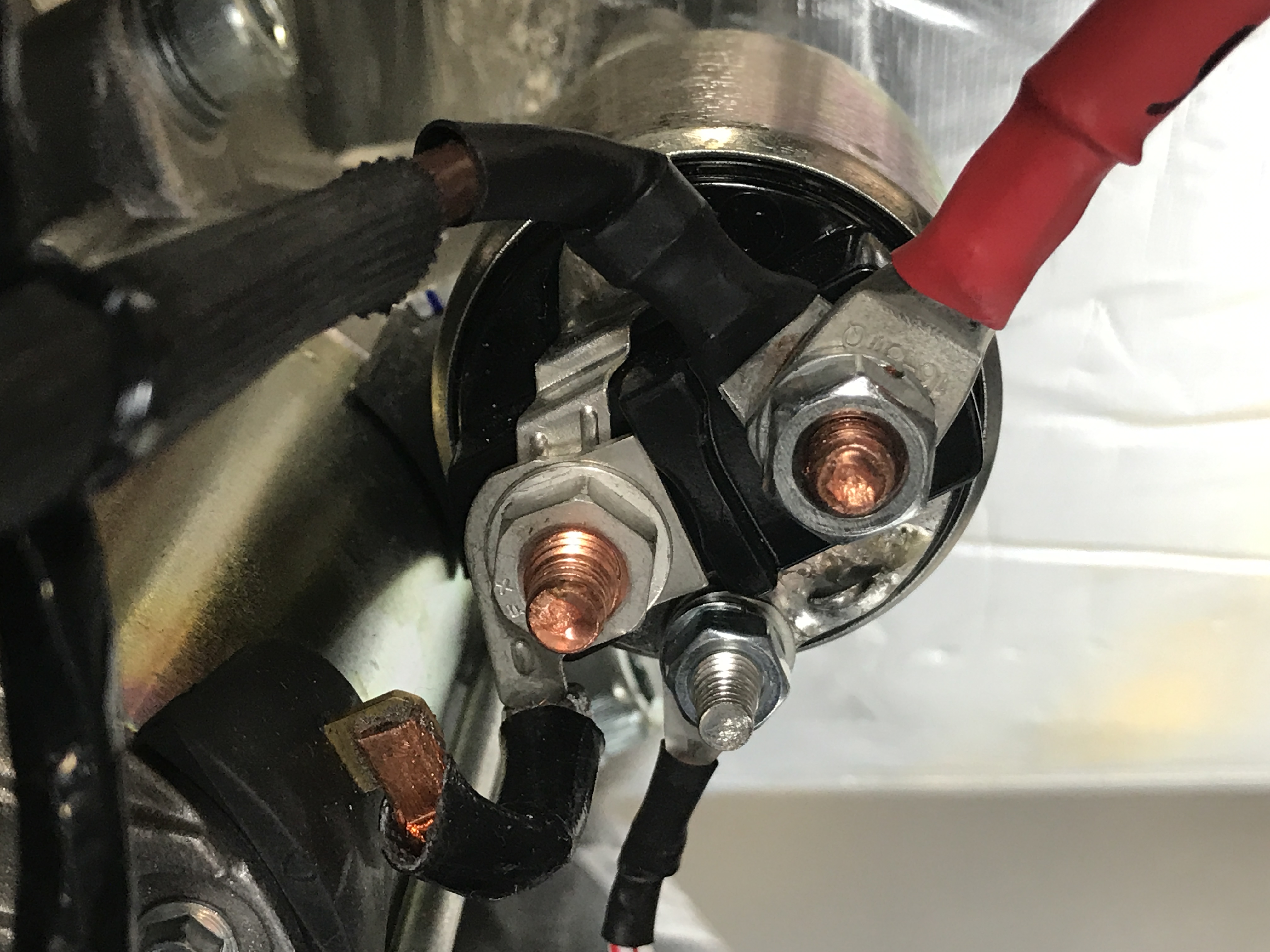
The manual talks about connecting brown wires to the starter and alternator. As far as I can tell this is all connected on our car. It’s just the 12v lead to the starter motor that’s required now. You can see the brown lead coming off the same terminal as the red 12v lead and then that goes to the alternator already.
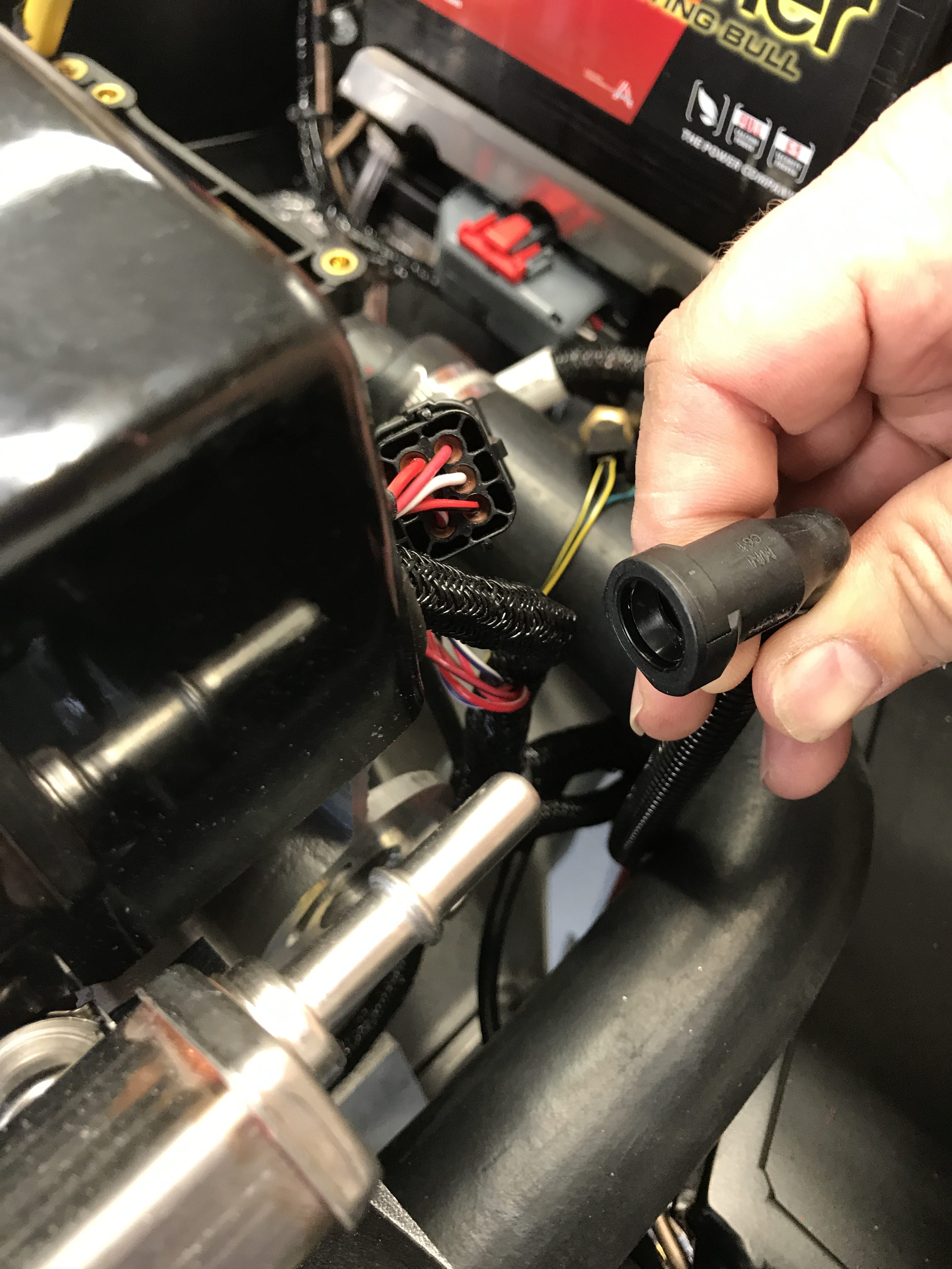
Fuel Pipe
Fuel Pipe next… this is a special locking connector. Apparently you need a special tool to take it off once it’s connected, so we made sure we weren’t impinging on any other wires as we slid the fuel pipe connector home. I’m not sure what’s so special about a tool that’s needed to take this plug off, that’ll require some research at a later date.
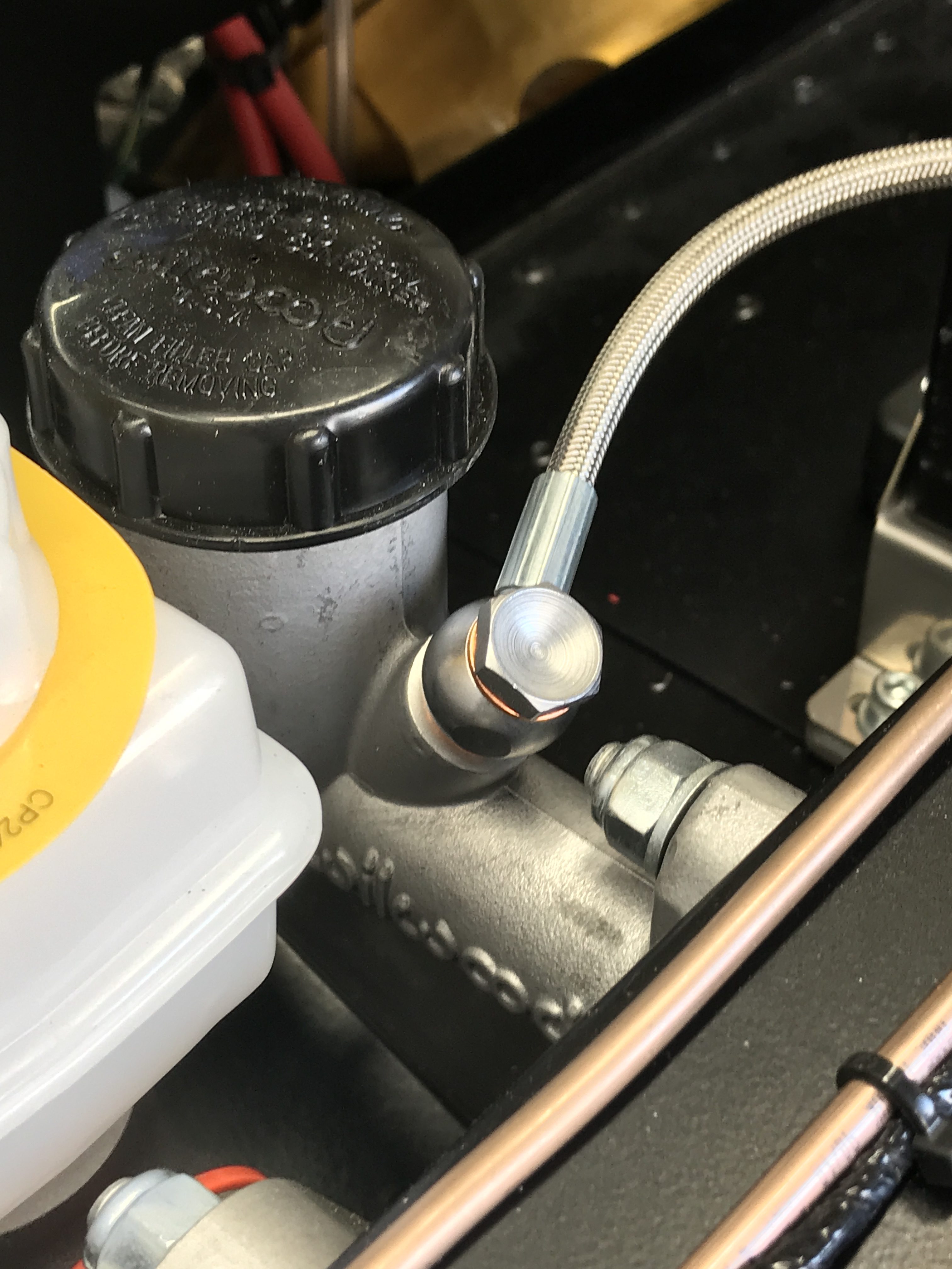
Clutch Hose Banjo
On to some hydraulics now. The braided hydraulic clutch hose uses a banjo connector to be attached to the clutch reservoir. There’s nothing much to get wrong here, however, the manual calls for protective shroud to be used on the clutch hose and I haven’t figured out the best way to do this – I suspect it will be cutoff section from the water expansion bottle 5/16″ hose (that’s what I’ve seen on other builds). I’ll post pictures of that in an engine tidy-up post letter in the build.
I’ve left all of the cables and pipes loose in the engine bay at the moment, and intend to leave them loose going forwards, until the last minute. It seems that there are plenty of options for tying things down in the engine bay and for routing cables and pipes. I don’t want to spend time tying something down only to find it fouls something else later or there’s a better option that comes to light. So, there’ll be a task to tidy up the engine bay in a later session.

Leave a Comment