

Now back from the US and the after effects of hurricane Irma… I have some more time to get on with the build. I’d left the project at the point where I really needed to get on with the engine bay plumbing and I’d laid all the hoses out in the engine bay prior to the trip. The 5/16th” water expansion bottle hose was missing from the kit but while I was in the US I’d emailed Derek and the hose had arrived while I was away… so first task was Water Expansion Bottle.
Water Expansion Bottle
I’d mentioned before that I wanted to get the bracket for this bottle sorted in my mind and where it was going to go – that had led me to test fitting the bonnet and the nose cone to test that where I wanted to the expansion bottle was going to fit under the bonnet.
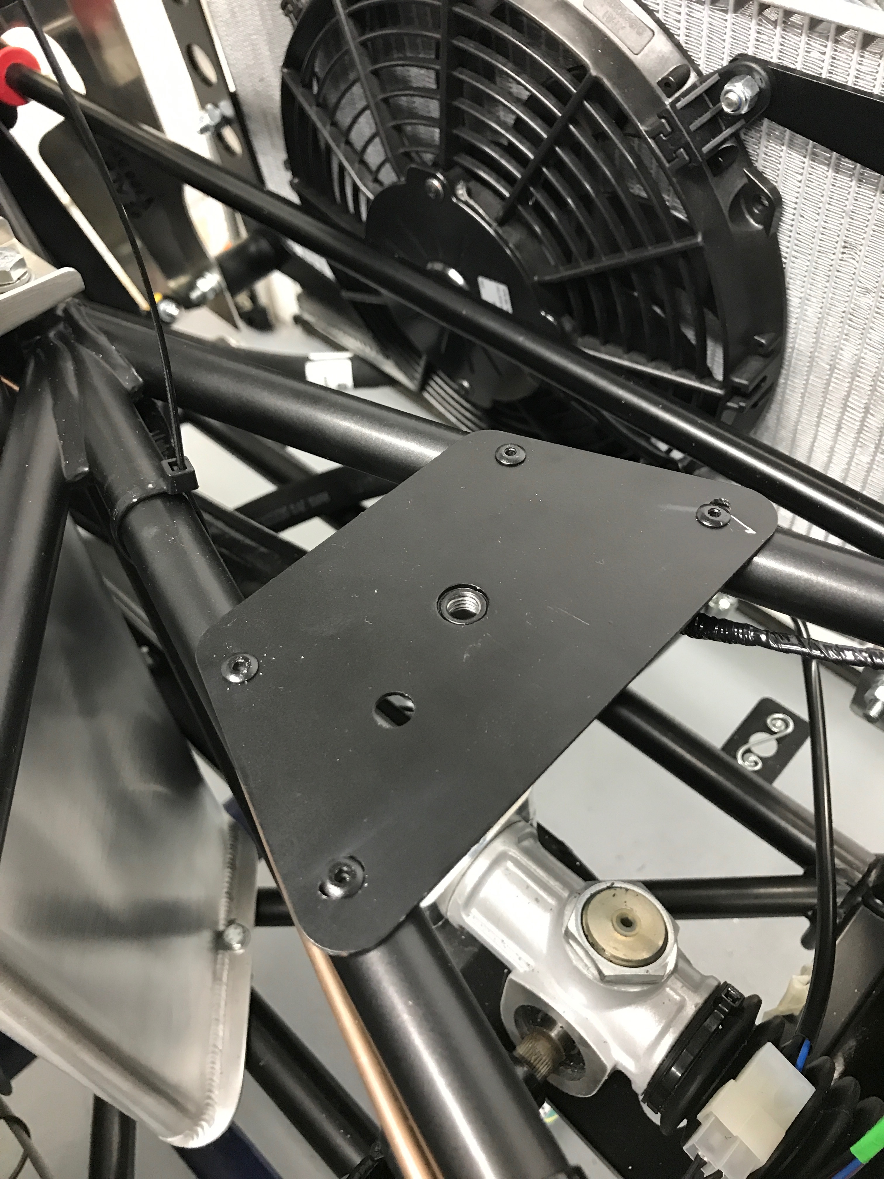
So, now I have that set I drilled the holes for the rivets (no rivnuts here) and removed the cable ties that are going to get in the way. I’ll have to re-tie the cables later.
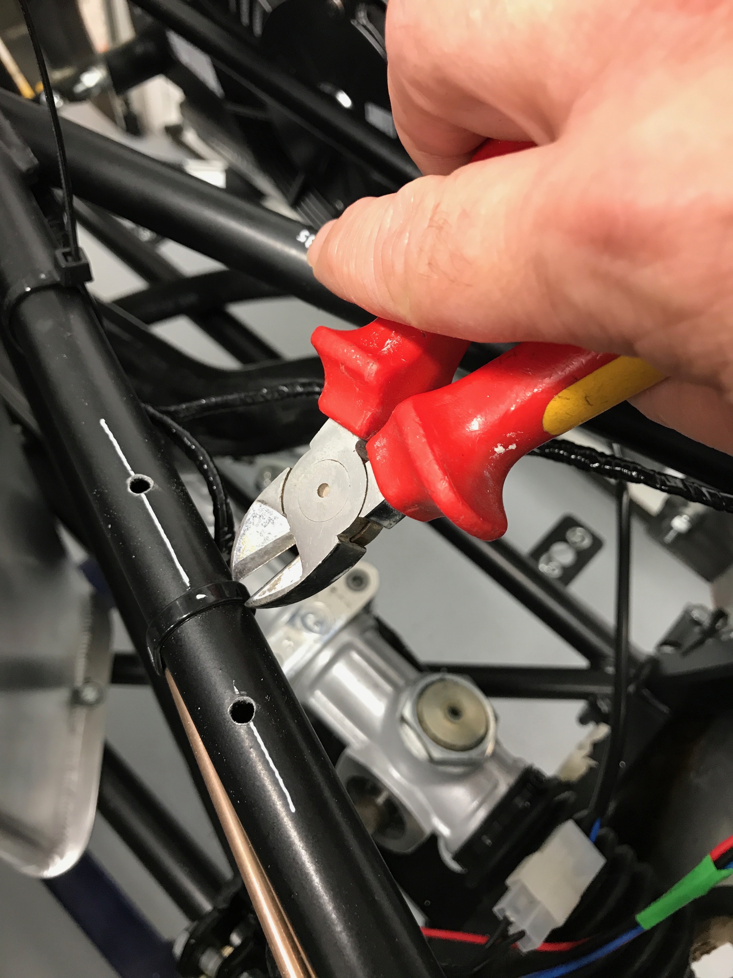
I decided that I wanted to the rivets to sit vertically on the rails and not have to drill diagonally into the rails. That meant I had to open up the two outboard holes in the bracket. I’d set the bracket on the chassis rails so the inboard holes could be left alone, but that meant slots needed to be created in the outboard ones.
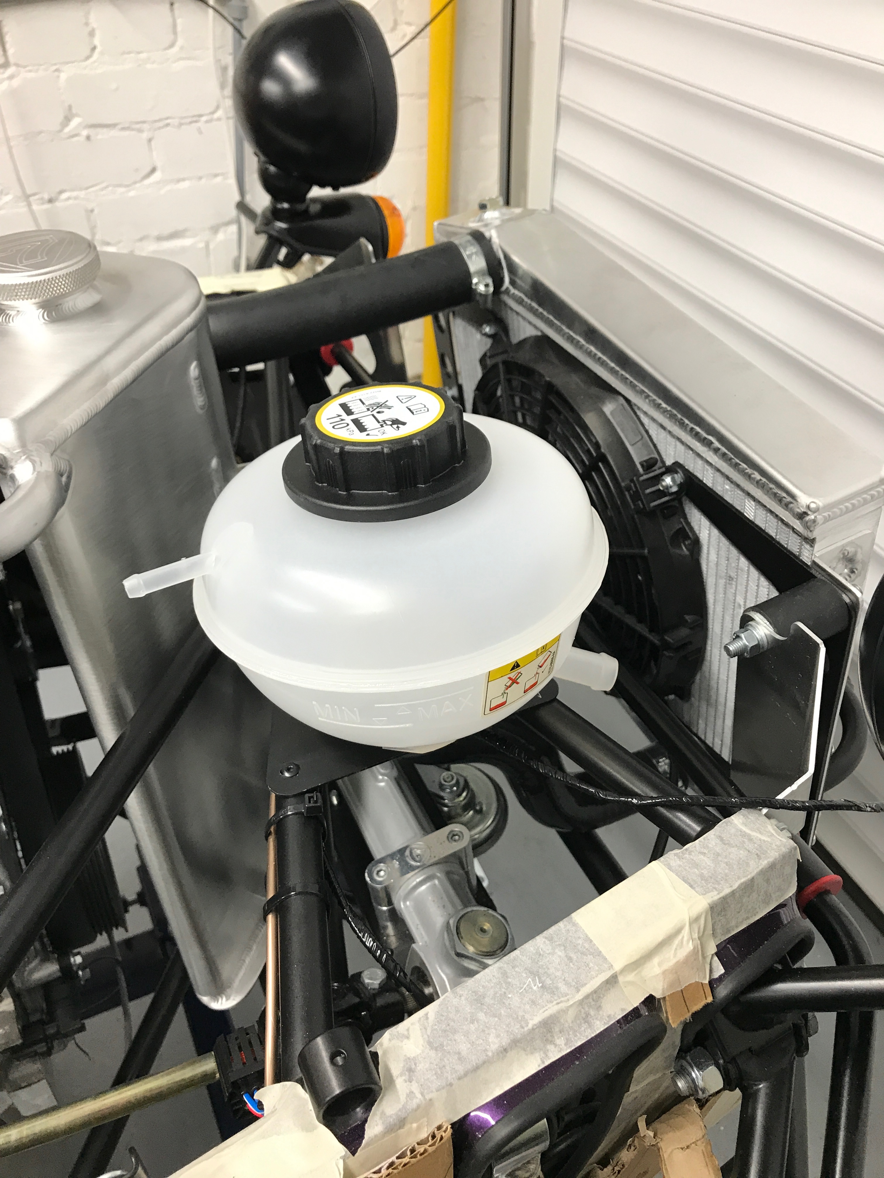
Now for another conundrum… or two conundrums actually. Firstly, what orientation should the expansion bottle be. Secondly, where to route the 5/16th” cable from the water bottle to the back of the cylinder head.
In most of the builds I’ve seen, the water expansion bottle is placed so that the 5/16th hose comes out directly rearwards. That means the main water hose can come out of the front-right of the bottle towards the front right chassis corner. However, while this config means the 5/16th hose routes easily across the top of the hot side of the engine, it also means the main water hose has to bend a long way backwards to get back across the front of the engine bay.
The other complexity here is that he build manual talks about routing the 5/16th” hose around the front and then the cold side of the engine and then back around the back of the engine. That makes sense I guess, the primaries are going to get really hot and any water in the 5/16th hose is going to be really really hot as it sits in that pipe. Hmmm.
So, I decided to site the water bottle with the 5/16th outlet pointing directly rearwards. However, I would try routing the hose as suggested in the manual… easier to do this while the hose was long rather than cutting it down and then realising I wanted it routed differently ;-).
Now to route the hoses and see what I think of that.
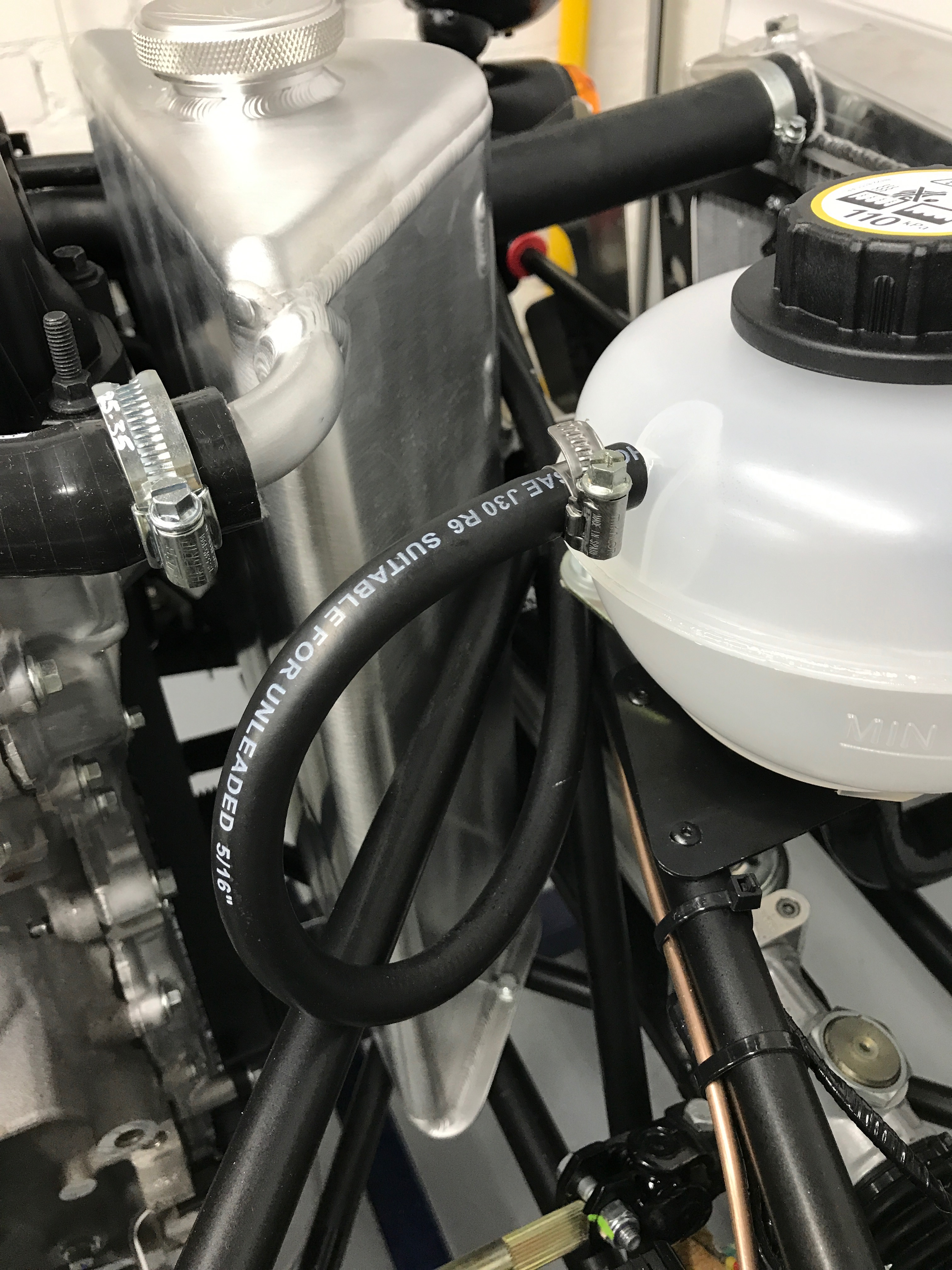
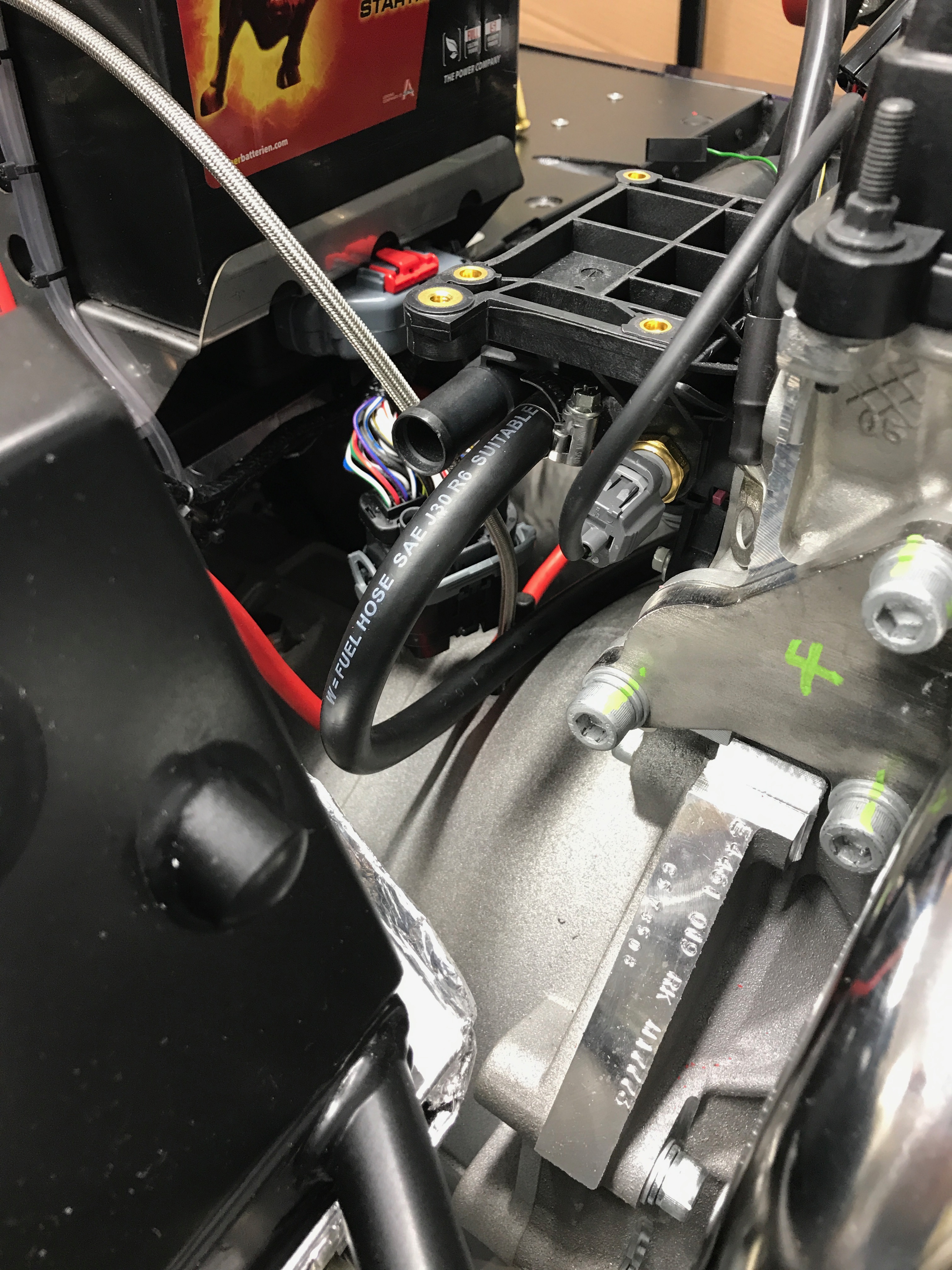
Hmmm… if using all the hose up was an objective, then I certainly achieved that.
The other thing to add to the equation here is that I’ve seen posts and pictures of Caterham built cars where some of this 5/16th fuel hose (it’s actually labelled as fuel hose) is used as a shroud for the braided clutch hose and also in some cases to protect the rear brake hose from abrasion too.
Hmmm… (again)… I’m going to need to re-route this 5/16th hose around the hot side I think and give myself some spare hose for other tasks.
Onto something else while I ponder that one though…
Heater Plumbing
Time to fit the heater… I’d had it sat loosely in the car for a couple of weeks but it was now time to figure out how the plumbing was going to work and how the heater control valve gets connected up.
First job was to finally bolt the heater in place.

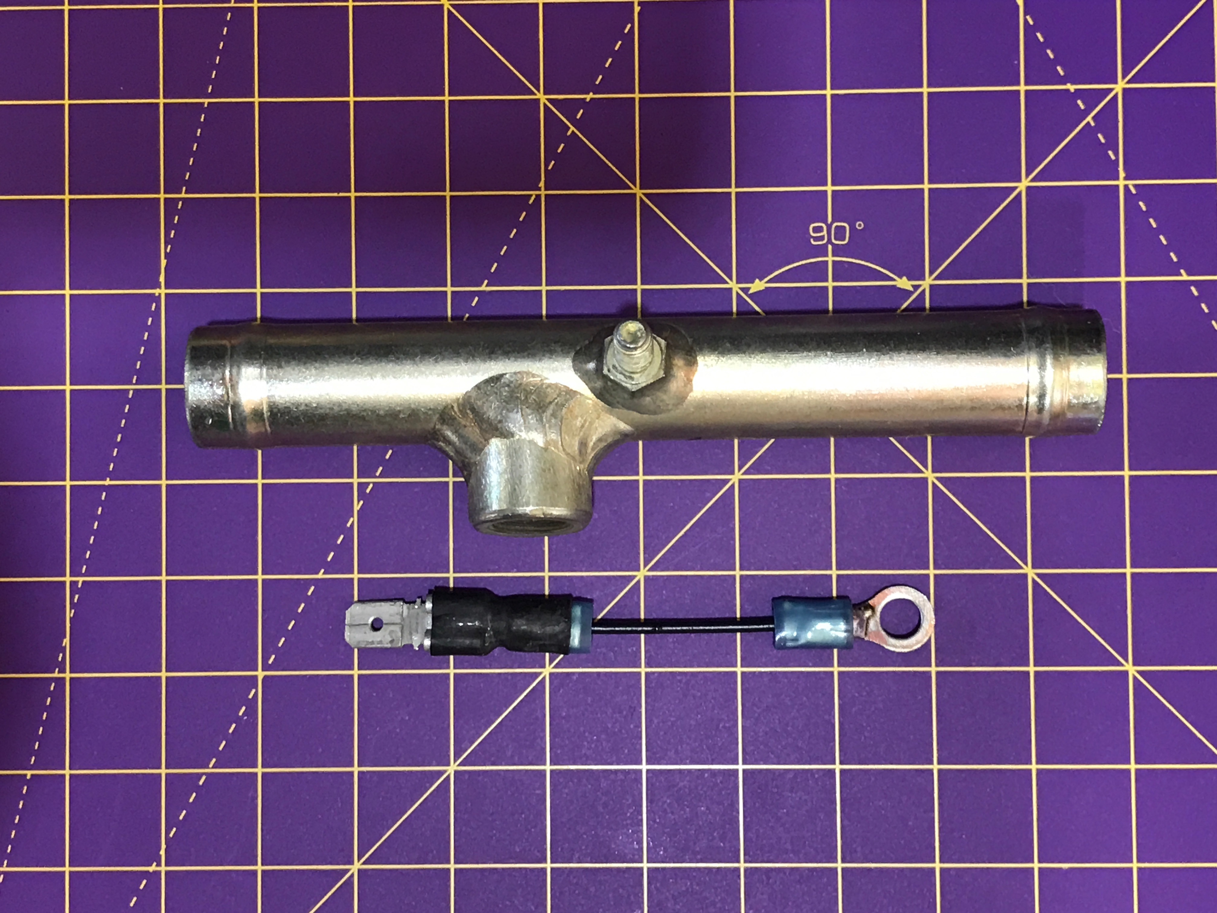
In order to get the heater pipework in I decided I needed to get more of the rest of the plumbing in place too. It was a case of “a bit here, a bit there”. Next I installed the T-piece that goes into the water inlet on the front of the engine.
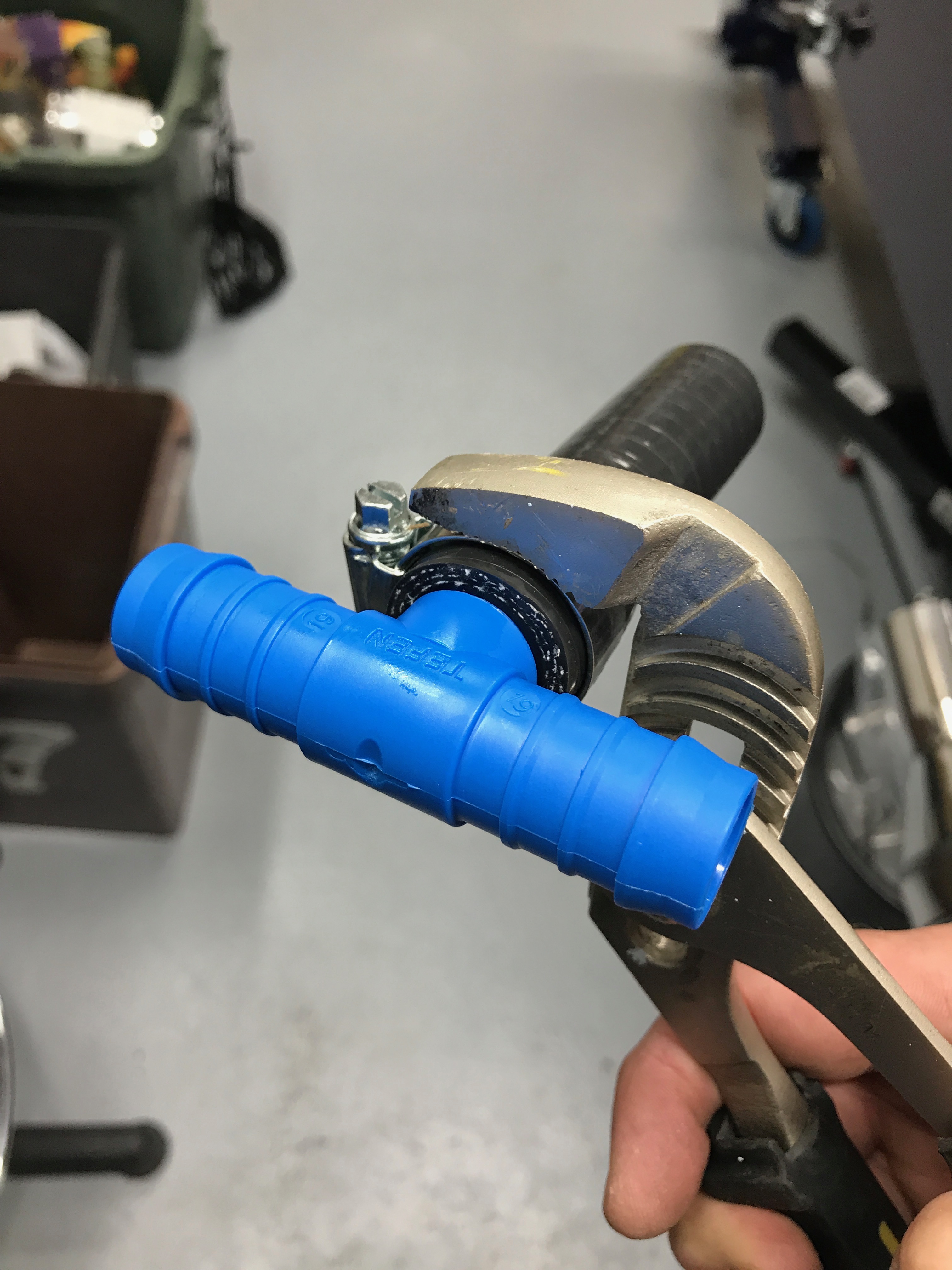

Next up I need to work out how the J-hose runs from the back of the cylinder head (next to the 5/16th expansion bottle hose) and connects to the lower heater control valve connection. This run of hose also needs to get cut and the water temperature (submarine) inserted inline. So… now I need to figure out where to position the submarine.
There are lots of pictures of people installing the submarine into a Seven engine bay. The way that Caterham seem to do it now is as follows:
- Connect the J-hose to the rear of the cylinder head (there’s only one port of the right size, the other one is for the 5/16th water expansion hose)
- Run the J-hose under the cylinder head ports
- Place the submarine inline towards the left hand side of the car
- Run the LHS of the submarine to the lower heater control valve port.
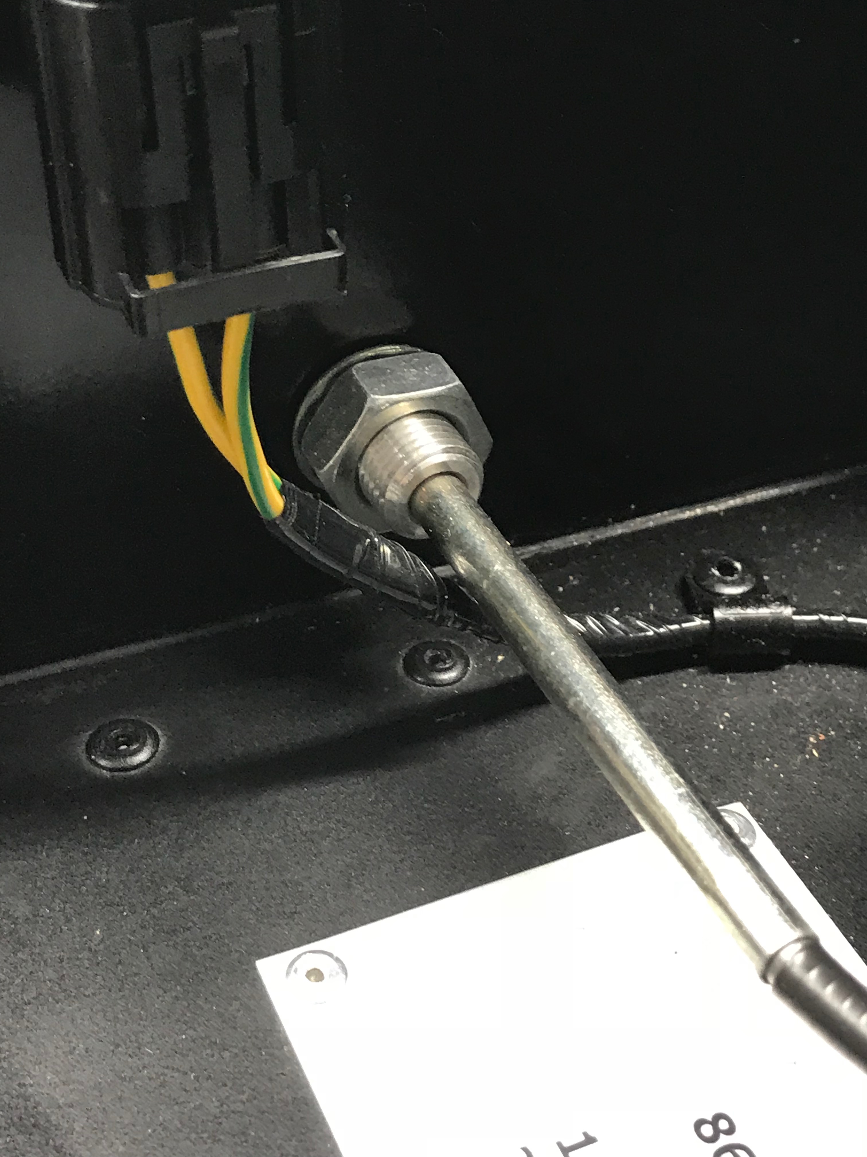
I’ve seen various people post about how to connect the earth (threaded post) to the spade connector (green and blue lead) on the loom. My kit also came with the temperature sensor connected but dangling on the spade connector (black and yellow lead). I searched the kit for something that would allow me to put a ring terminal and spade connection onto the earth threaded post but I couldn’t find anything. I didn’t want to bother Derek with this one so made up my own lead with a crimp tool.
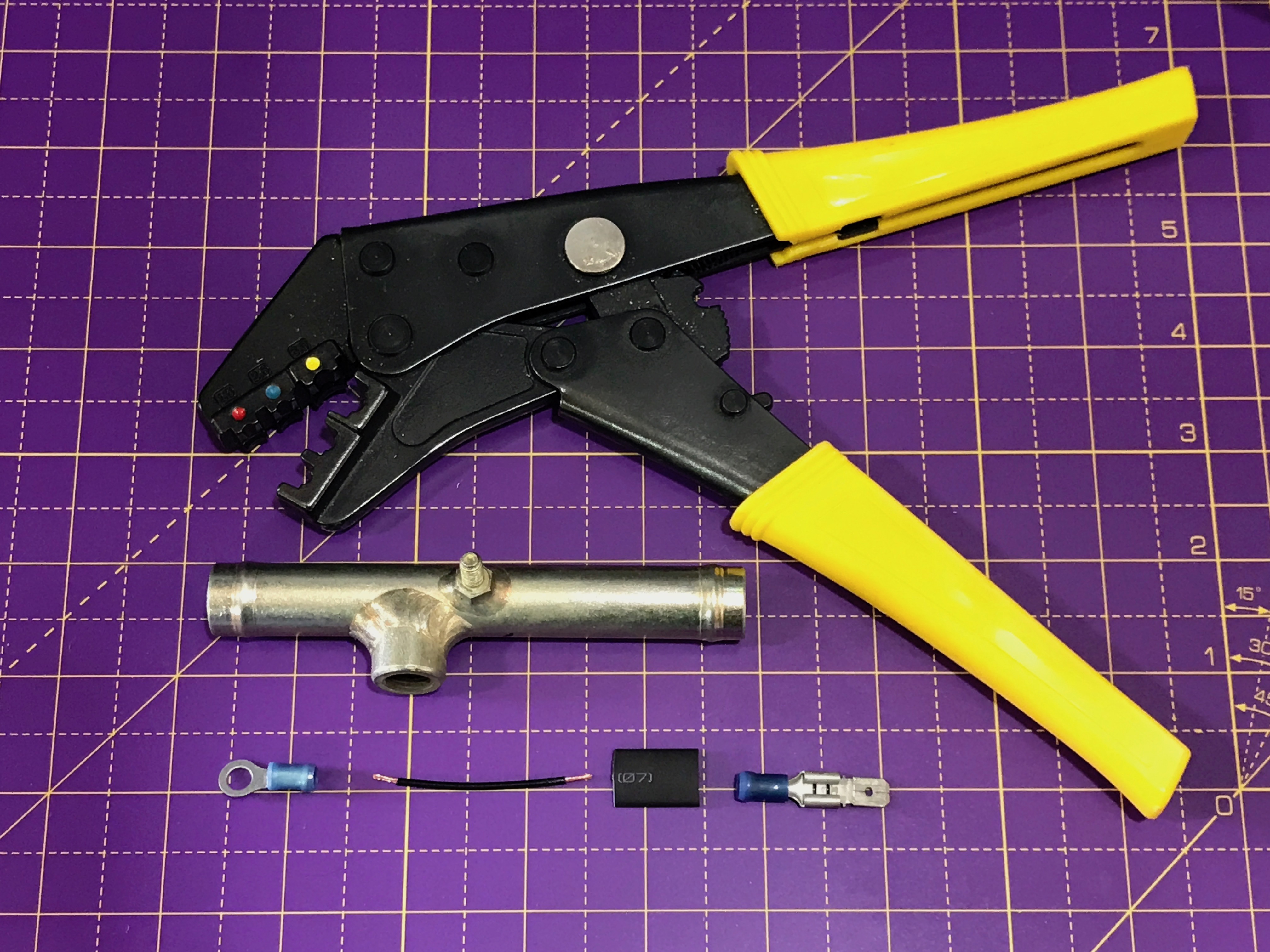
And this is what the lead looked like when it was finished.
And then installed…
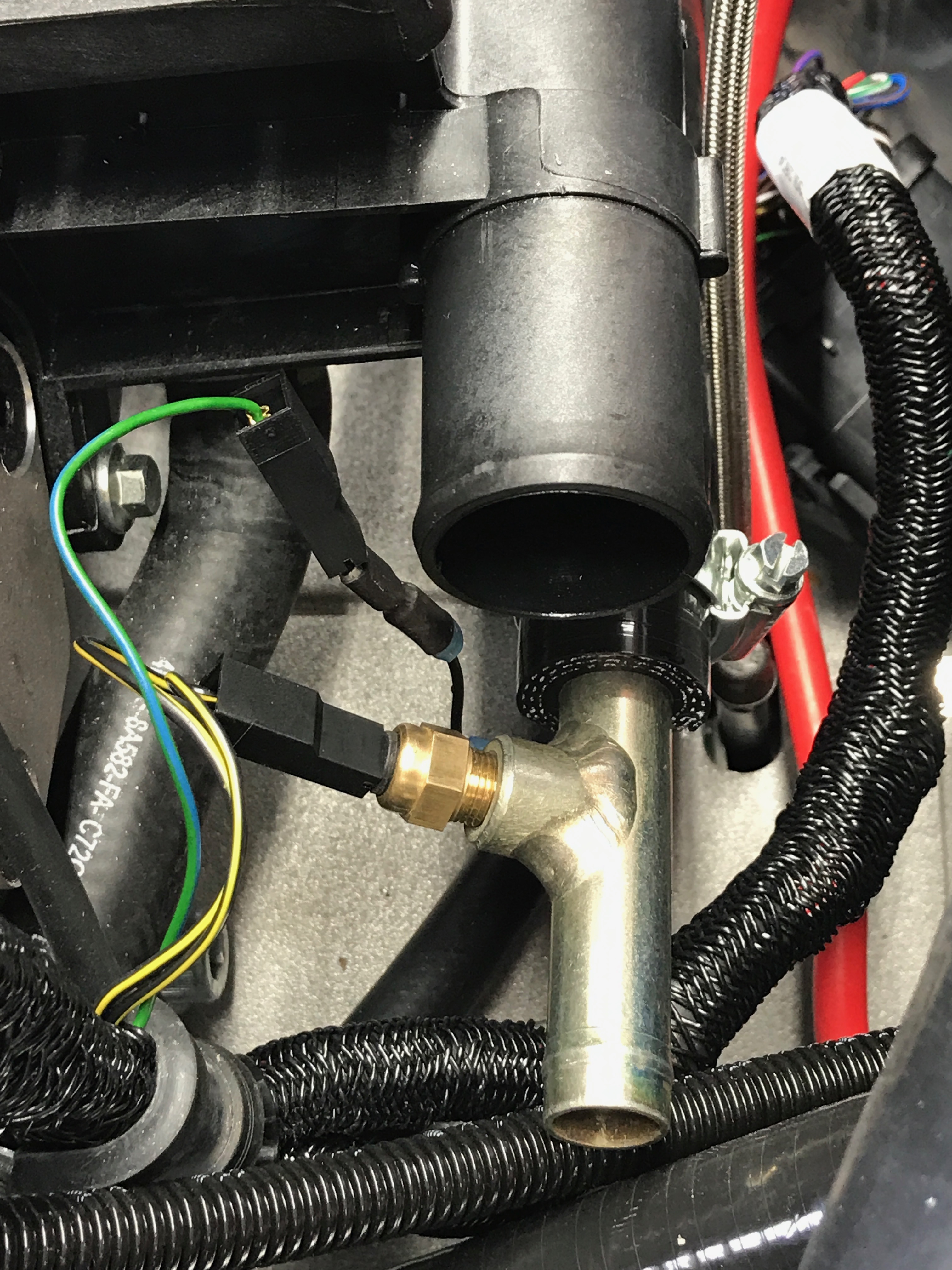
At this point we have the hose from the expansion bottle connecting through the T-piece. And we have the J-hose feeding underneath the back of the cylinder head and through the submarine. The next task is to put the heater control valve in place and hook up these two connections from the submarine and T-piece.
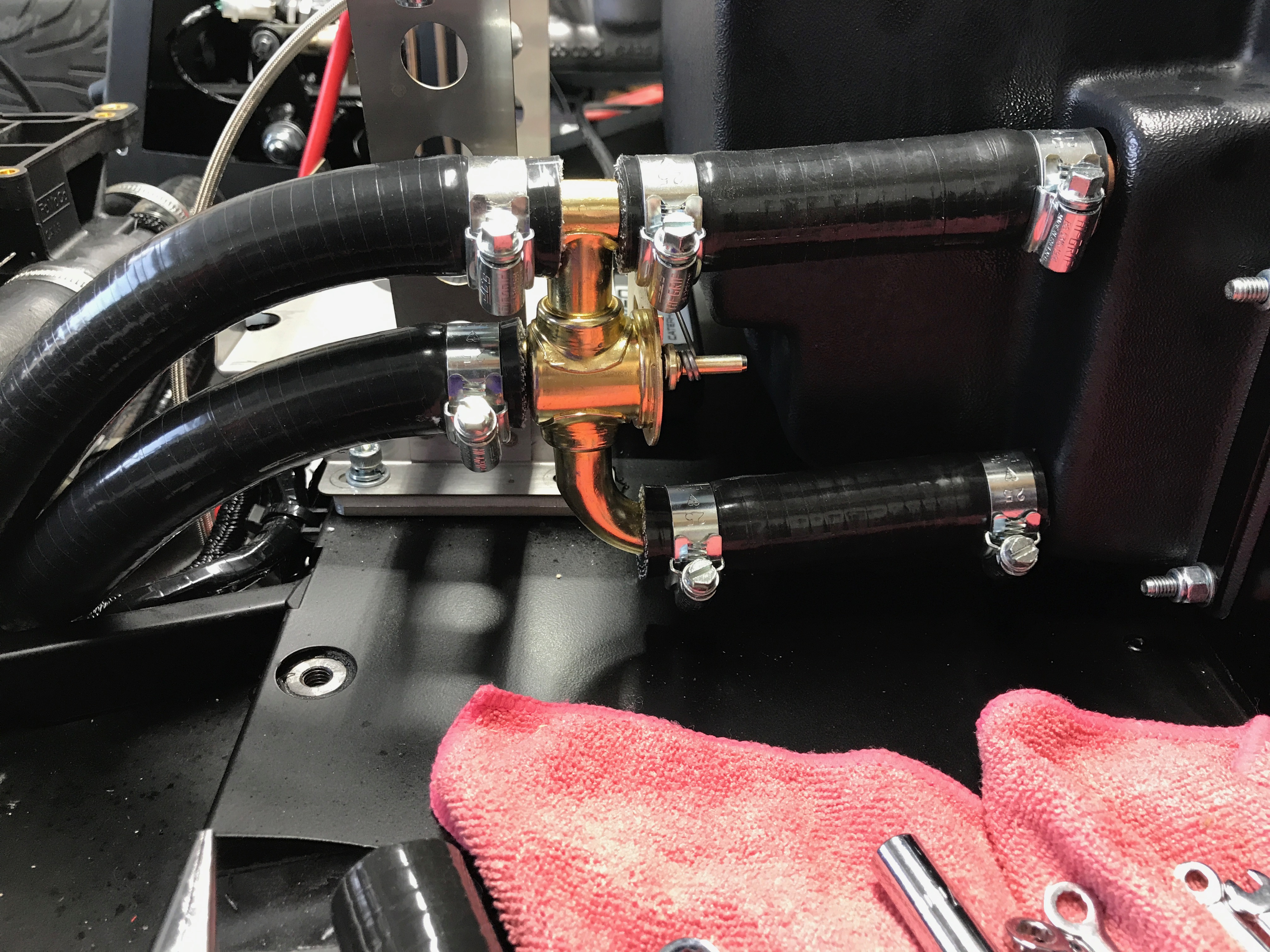
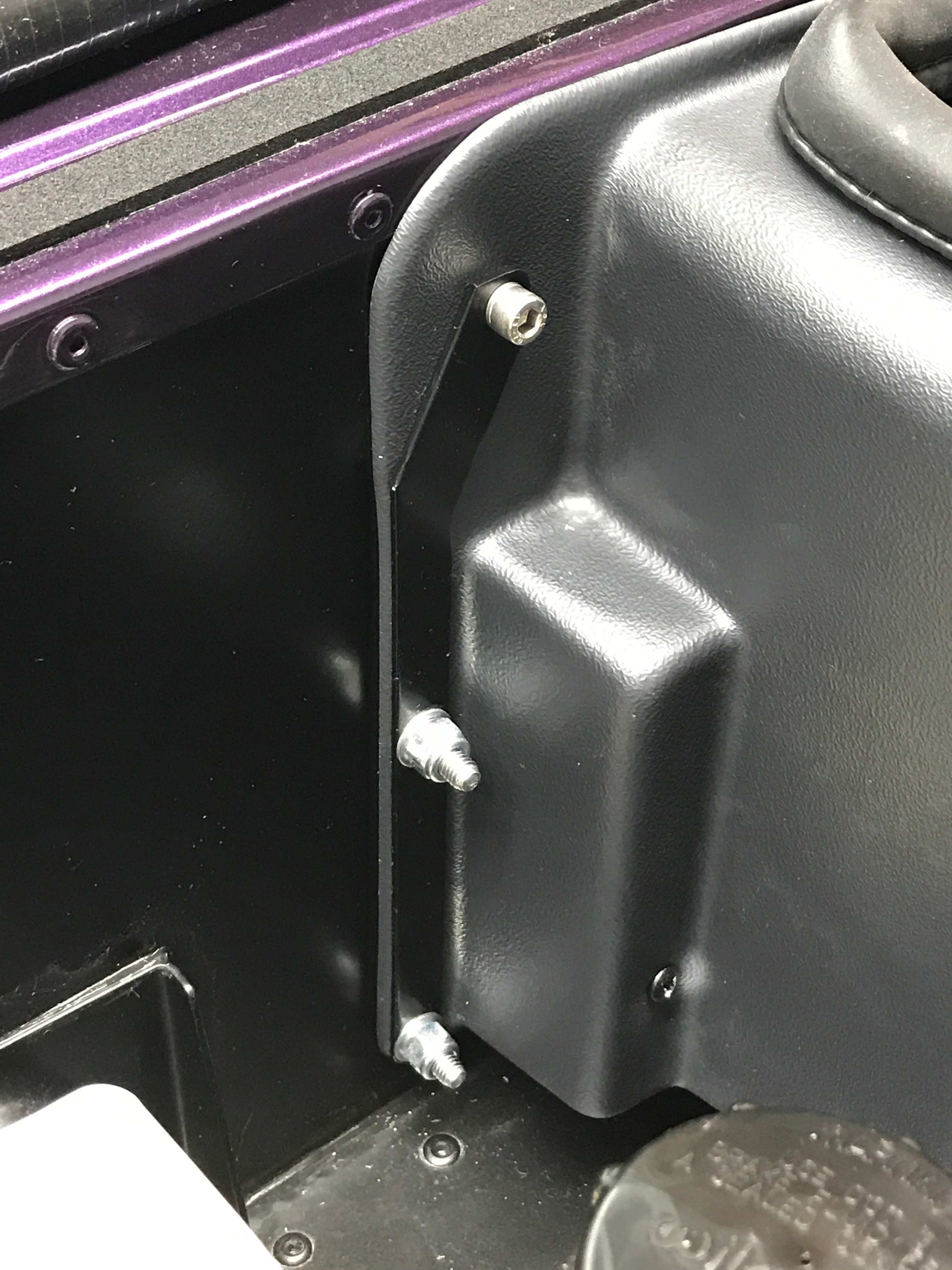
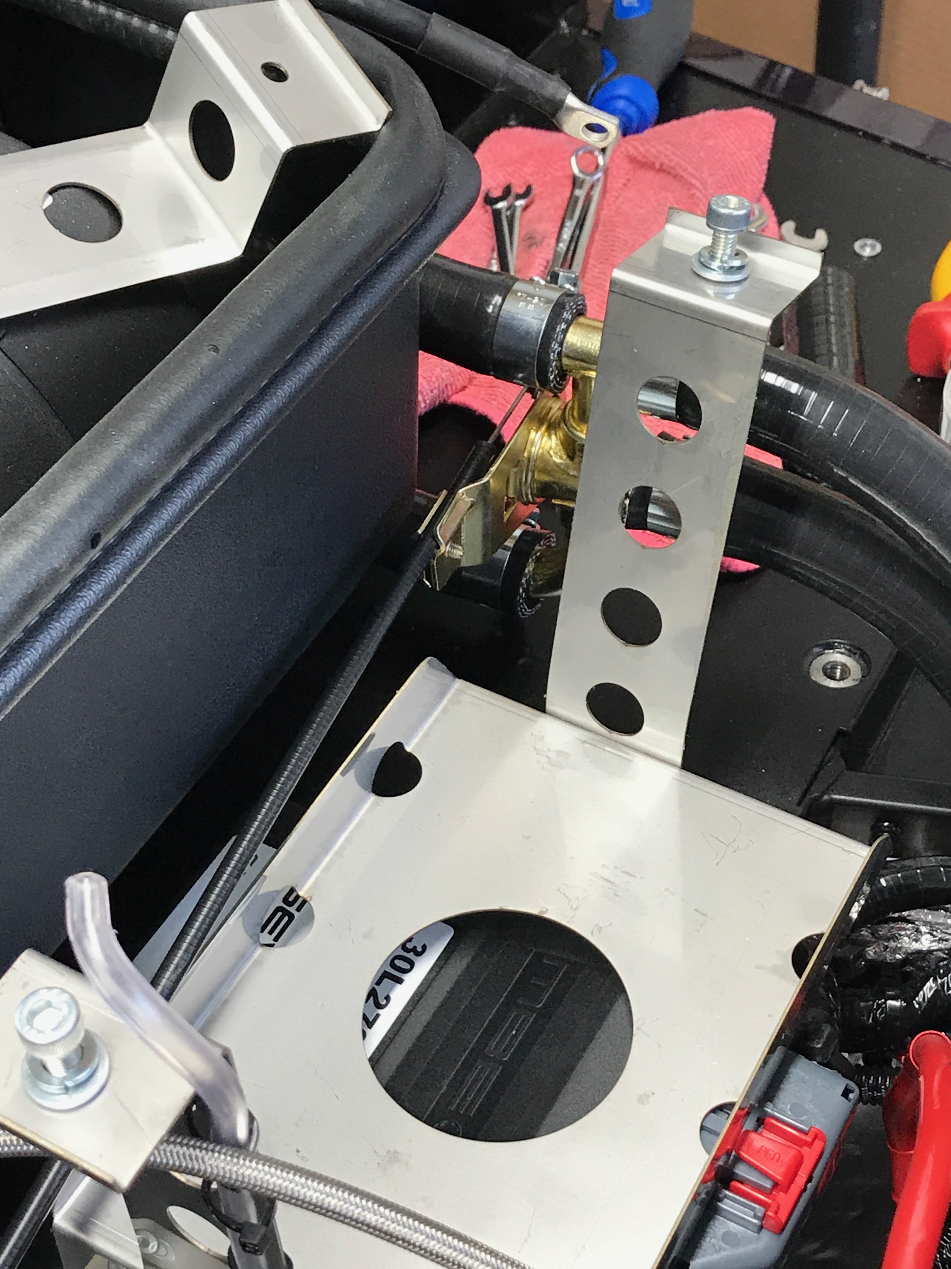
The heater valve needs to be placed so that the control cable, running to the driver’s side firewall, needs to pass between the battery and the heater blower assembly.
Once I’d got all the hoses connected to the heater valve I wasn’t so keen to take them all off again. So… to get the control cable attached to the valve I found it easier to take the battery out and give me better access to the screw and clasp that the cable route to.
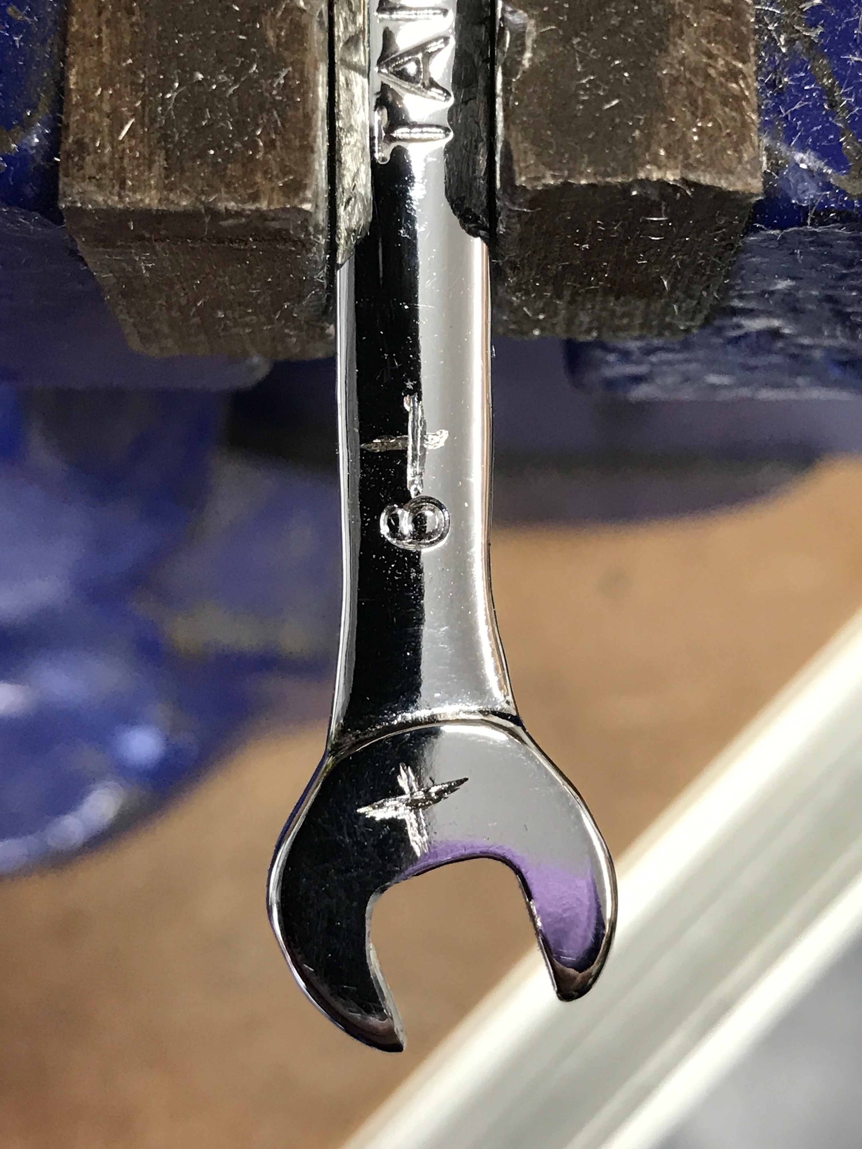
One oddity was that the screw on the clasp retaining the cable shroud seemed to be an odd size. It was bigger than a 6mm spanner but smaller than a 7mm. I ended up grinding a 6mm spanner to size. It’s probably imperial but I don’t have imperial spanners that go that small.
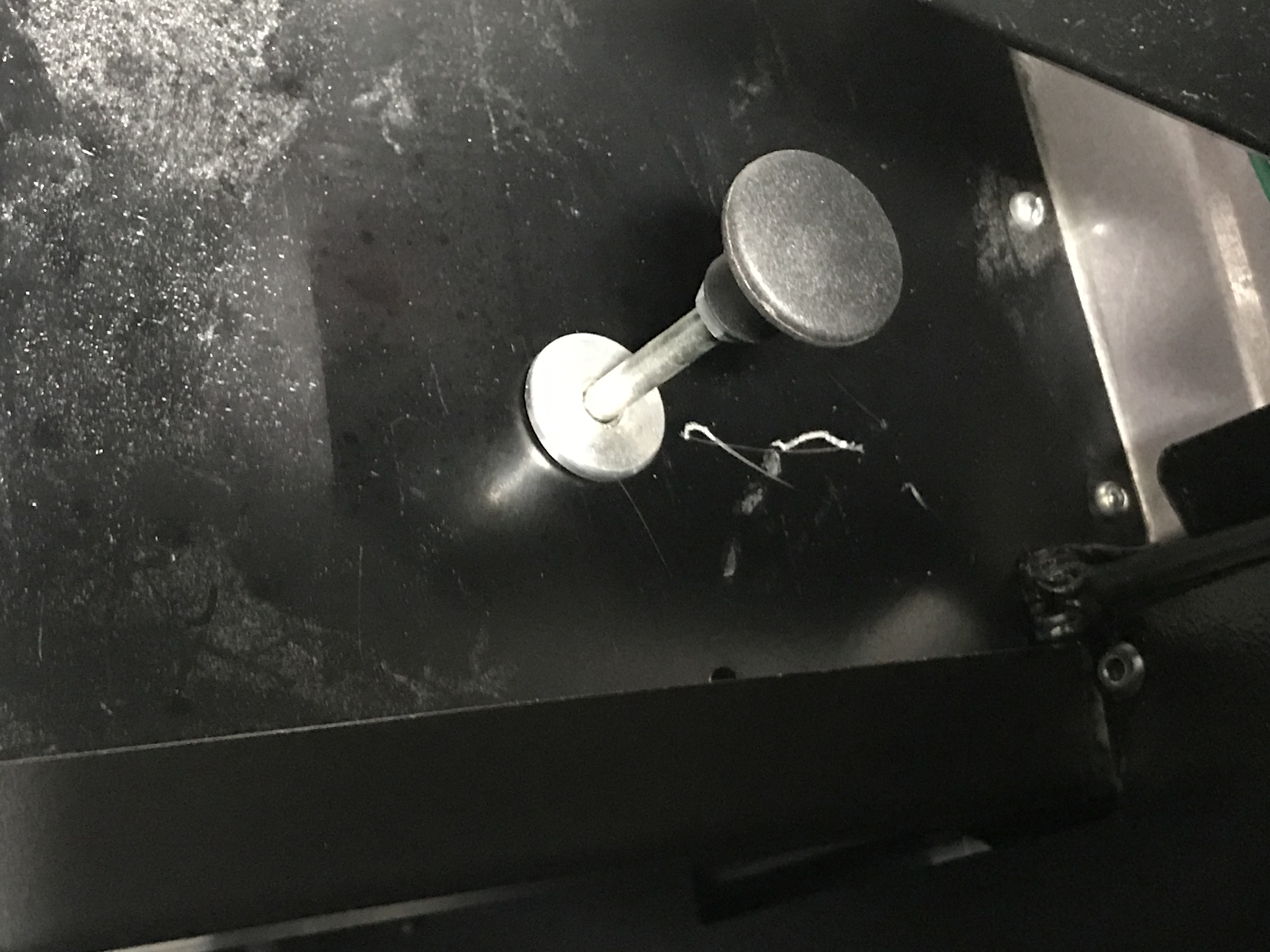
It was simple to install the heater control knob into the firewall on the driver’s side.
Oil Hoses Tightened
While I was thinking about plumbing I tightened up the oil hoses to/from the oil radiator, block and oil tank.
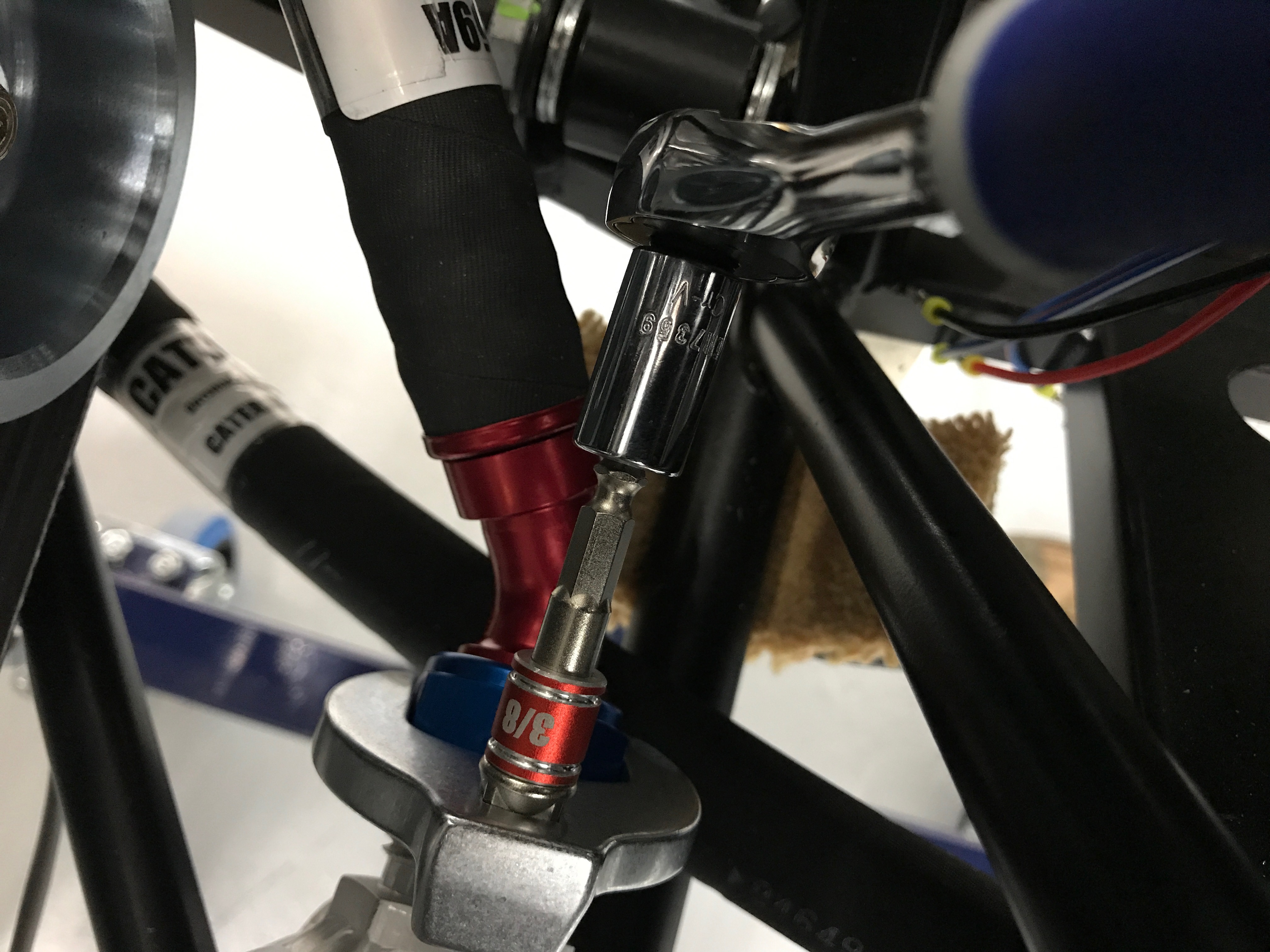
Some of the hoses were a little tricky to get to at this stage of the build and getting a torque wrench onto them was even trickier. The crows feet spanners came in handy with a mix-up of extension bars thrown in for good measure.
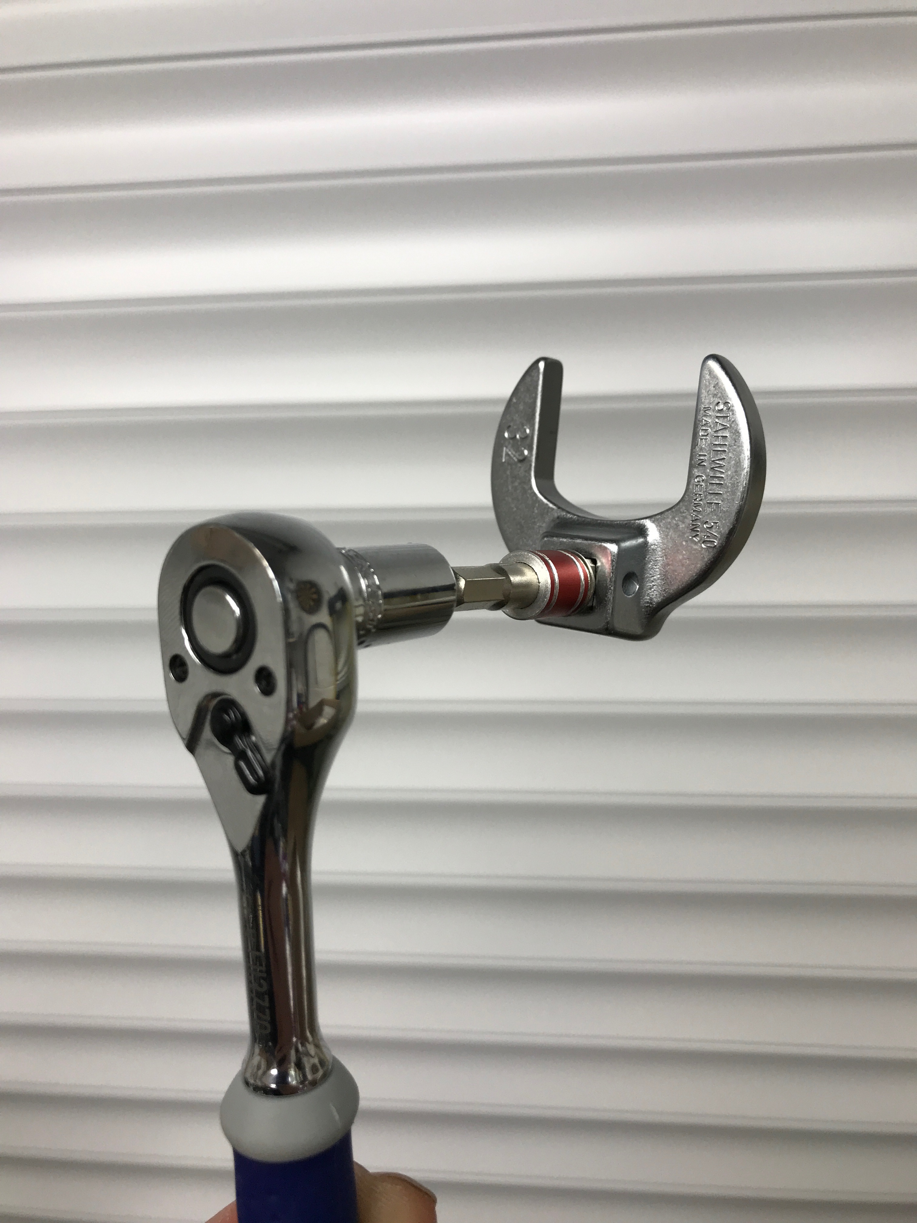
Once I needed to torque the oil hoses I derated the torque values on the wrench by the 5% fudge factor required because the centre of rotation of the crows foot increases the effective length of the wrench by 5%. This calculation only works if the crows foot is as in the photo above. If the crows foot is 90° to that shown in the photo then there’s no fudge factor needed but that’s not always the right configuration for the space you have.

That was the end of the day and most of the engine bay plumbing done. It’ll be working towards the rear of the car tomorrow with the prop-shaft and diff hopefully being fitted.

Leave a Comment