
Another one of those bitty weeks. Not much time to really get my teeth stuck into anything but got a couple of odd jobs done.
Earth Leads
First off was a go at the battery earth leads….
There are three leads that I needed to take a look at:
- Battery to engine
- Chassis to engine
- Battery to chassis
The build manual only talks about the first two of these connections. It says to attach the battery-to-engine earth lead from the battery to the bell housing. I guess this makes sense but I didn’t want to undo the bell housing bolts just to put an earth lead on.
There was a similar logic going on with the engine mount (LHS chassis) to engine earth lead. The manual suggests attaching this to the engine mount strut on the engine. That’s a perfectly sensible place to put it… and in the absolute cause of “adding lightness” I can see that using existing bolts for both the bell housing connection and the engine mount connection makes sense. However, two extra bolts is not going to break the bank so I decided to use existing empty holes in the LHS of the engine and to connect these two earth leads there instead.
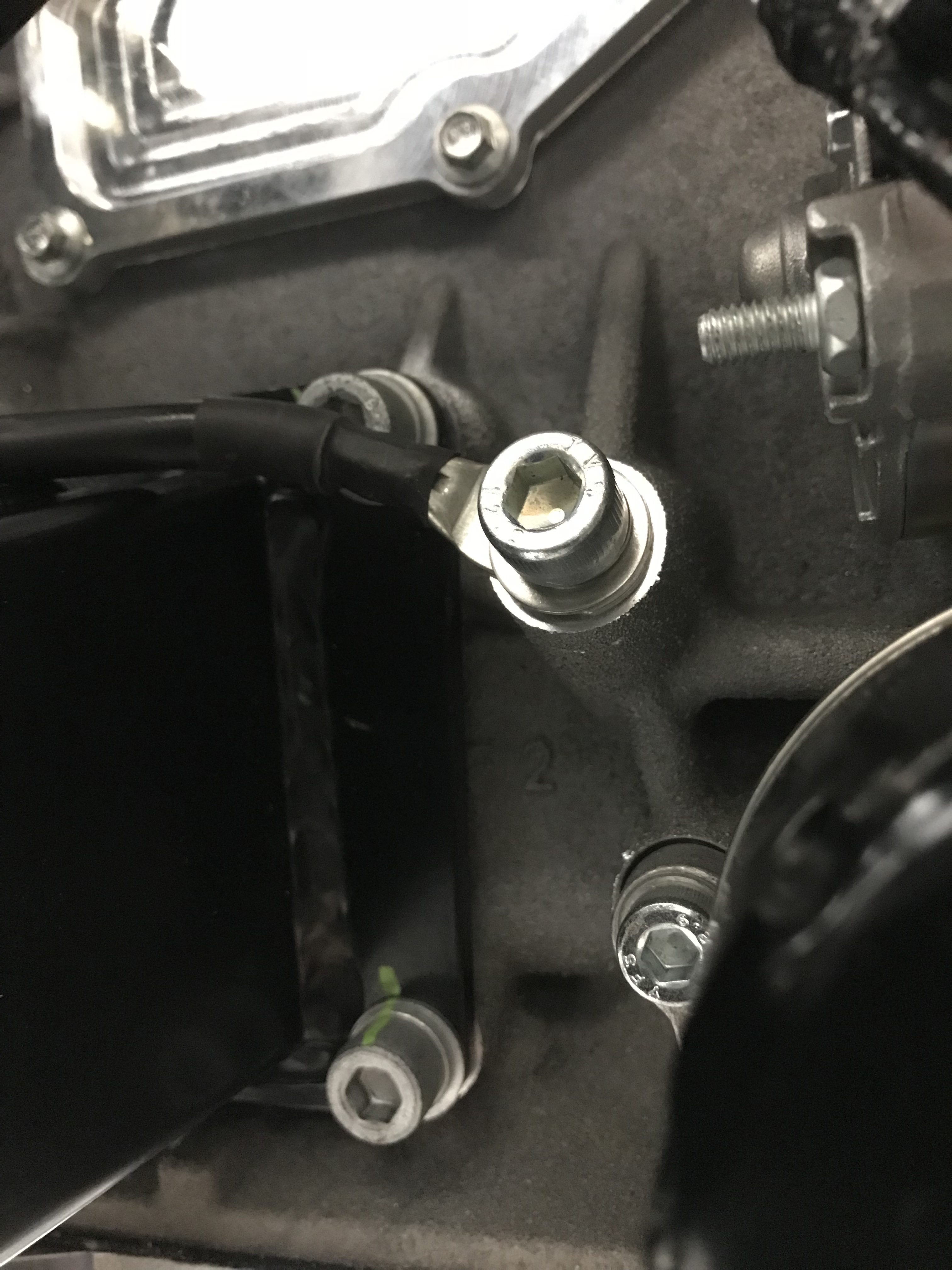
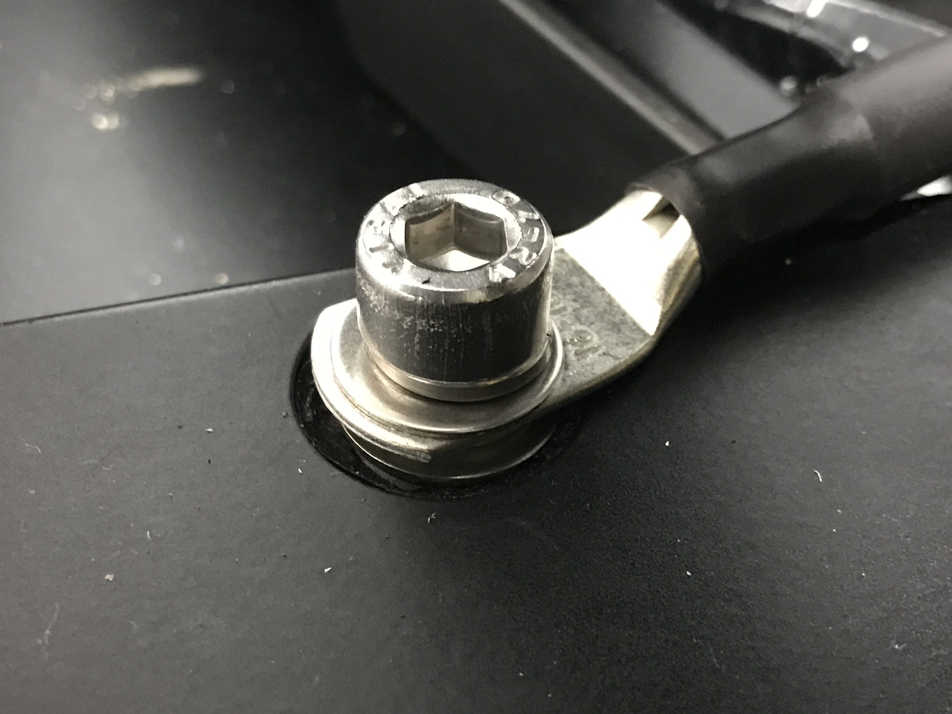
I’d taken delivery of some M8 cap head bolts this week so it made sense to get these leads fixed up one evening (one was M8 the other M6).

A note from the future: after talking to Andrew Pepperrell about his build… he had got to the earth lead bit and wasn’t keen to undo his engine mounts to attach the lead either. He asked Caterham what to do and was told that the LHS engine mount earth lead was not strictly necessary. I can certainly see that having multiple connections to the chassis is not a requirement, but since I had decided to go with the belt and braces approach I didn’t see the need to remove anything.
There’s also the third battery lead to connect these days. The build manual doesn’t talk about this lead but I’d seen it connected on the few 420’s I’d managed to take a look at and I guess Caterham have their reasons. It c certainly would save the effort of stripping the paint away from the chassis engine mount. For this third lead it connects from the battery negative to a spare threaded hole where the pedal box would go on a left hand drive car, ie above my passenger side footwell.
To finish off the discussion about earth leads… I’ve talked about this before… A good earth to the chassis is cleary important – either directly via the LHS pedal box mount or indirectly through the battery to engine and then engine to chassis mount. However, the highest current path on the car is the circuit made up through the battery and starter motor. Therefore, its important to get low impedance (low resistance) connections from the battery to engine (earth connection) and the battery to starter motor (12v connection). The starter motor “earth’s” itself through its casing directly to the engine – so the current used by the starter motor to start the car flows from the battery positive terminal, through the cut-off switch, through the starter motor, then through the engine block and finally through the battery-to-engine earth lead back to the battery negative terminal.
For those readers that are not electrically minded that means you need nice thick red (12v) cables for the connections on the battery positive, through any cutoff switch and then to the starter motor. And… you need a nice thick black (0v) cable from the battery negative to the engine casing. In each of these connections the main failure points are the connections themselves, so while some of the terminals are soft copper, they do need to be tight. Not crazy tight… but the leads mustn’t be loose or else this will create a high resistance connection and the starter motor won’t get the current it needs and therefore won’t reliably start the car.
Oil Catch
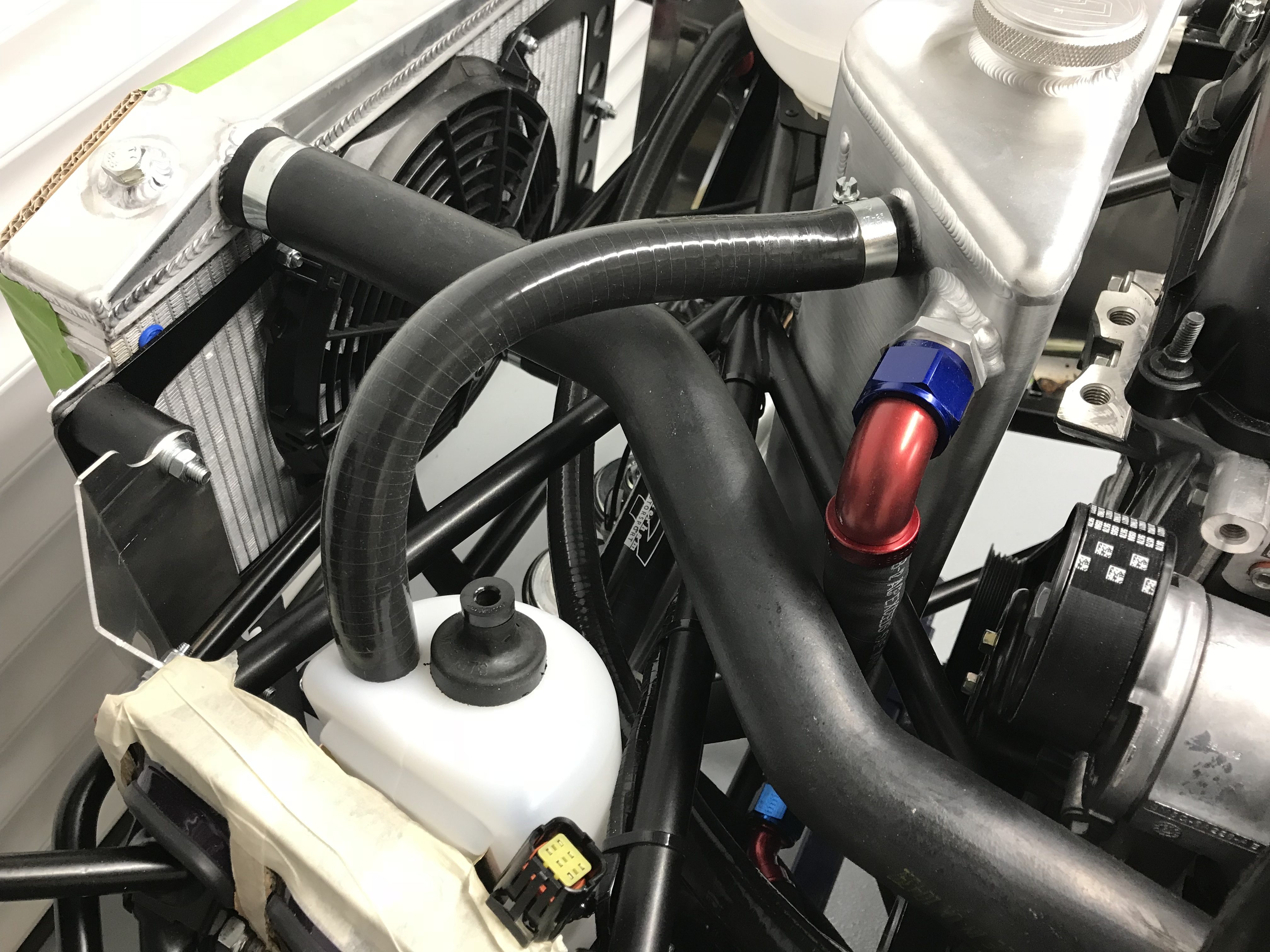
Another simple job was to sort out the oil connection from the triangular aluminium oil tank to the oil catch bottle now mounted on the LHS chassis rail near the radiators.
I’m not totally sure under what conditions this catch bottle comes into play. You’re supposed to connect this catch tank/bottle to the oil tank but also leave a hole in the bottle so it is open to the air. That means the oil system is running essentially at atmospheric pressure. So… I can’t see that there’s any pressure build up anywhere that would dump oil into this catch bottle.
Now I get to think about it… My current theory (and I’m totally open to being shot down here)… is that to keep things simple, the dry sump oil system only needs to run at something around atmospheric pressure. It also needs room for oil to expand into as it gets hotter. If you have expansion with no change in pressure then the volume has to change. i.e. the oil expands a little into the volume of the oil tank. If the oil system was not open to the air then pressure would increase as the oil got hotter. By putting a catch tank in you have a reservoir that’s removed from the main oil tank that is open to the air and means you don’t need any fancy pressure relief valves on the main oil tank. A consequence of this “open” system is that splashes of oil can reach the breather pipe at the top of the main oil tank and so you do end up with some oil ingress into the catch tank. We’ll see how much oil I actually get there and whether there is some scenario where oil is “forced” into the catch tank instead of just finding its way there.
Anyway, enough of the theorising… To connect the oil tank to the catch bottle I used a straight piece of hose from the J-hose left over from the water installation (28mm OD) and then drilled a 25mm hole in the top of the catch bottle.
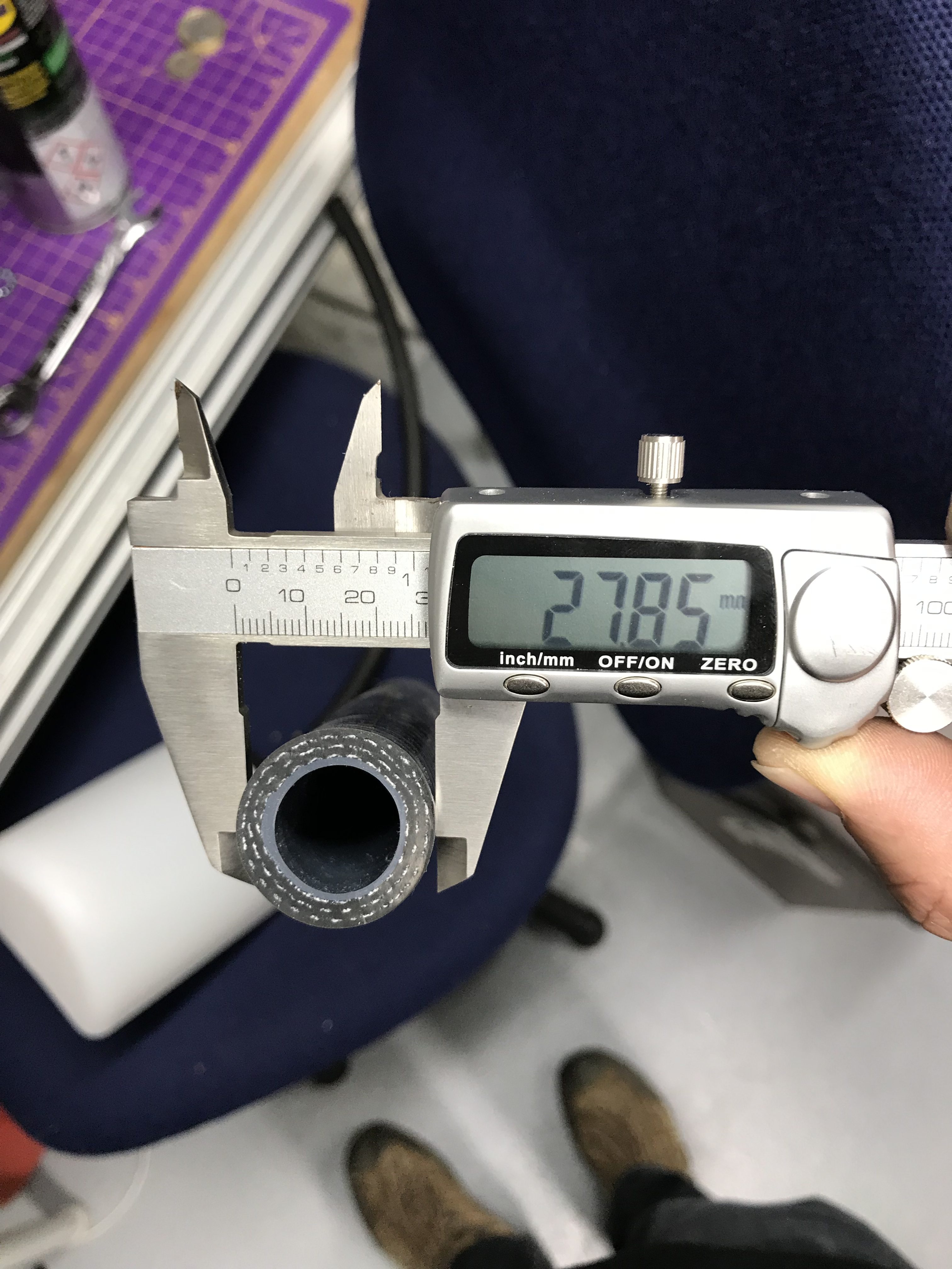
I made sure the 28mm hose went down a long way into the catch bottle. A) to stop it from coming out (it’s not glued or fixed in any way) and B) to stop any splashing of the oil I’m not expecting to end up in there!
So, I connected the 28mm OD hose from the main oil tank to the catch bottle through the snug 25mm hole I’d cut with a wood spade drill bit. I then pulled off the hose that came with the catch bottle. This is about 500mm long and is a friction fit through the supplied centre cap on the bottle…. I’ll use this after the IVA test to duct fumes from the oil catch tank down under the car, but for the moment that would be an IVA fail… i.e. I think, if you have a pipe from the catch tank pointing at the road… then no matter how unlikely it is… there is a chance that oil could be dumped from the main oil tank, into the catch bottle and then out of the breather pipe and onto the road… very James Bond.
I have heard people complain that having the catch bottle vent directly into the engine bay can cause oil fumes to get into the passenger compartment. So, venting those fumes under the car makes sense, but can’t be done until IVA is over.
A note to non-regular readers: IVA stands for Individual Vehicle Approval and is an approximate 4 hour government test of a kit car (in this instance) to make sure it’s road-worthy before I can apply for it’s registration documents.
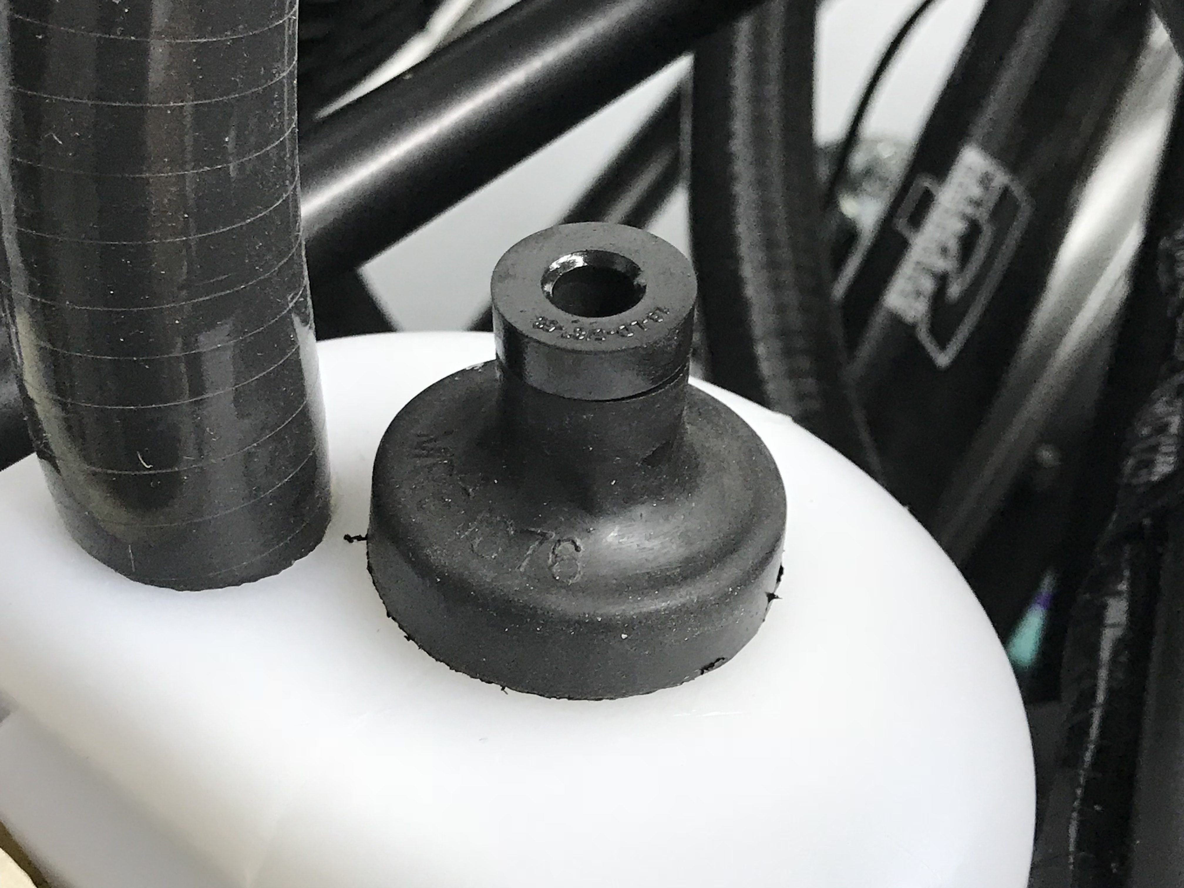
One final practical point here… having taken the hose out of the catch bottle that it came with, I didn’t like the fact that there was such a big hole left in the top of the bottle (the cap is still there though). So, I took one of the “bungs” that was protecting the heater unit from getting crud in it during shipping and stuffed that into the hole in the oil catch bottle cap. I pierced the bung to keep the whole system at atmospheric pressure but it all just looked a lot neater that way.
I’ve seen recent Caterham builds use a different cap on top of the bottle… with four small (~4mm??) holes in the cap. But… I couldn’t find a cap like that in my kit (with or without the holes) so I made do with the existing cap and the heater bung.
There’s a Hole in My Oil Tank, My Oil Tank, My Oil Tank…
I’ve probably mentioned this before but I was in a quandary as to what to do about a clear oil system failure at the bottom of the oil tank.
Clearly oil was just going to gush out of the hole pictured below and I couldn’t see anything in the build manual about what to do about it, nor could I find anything to plug the hole.
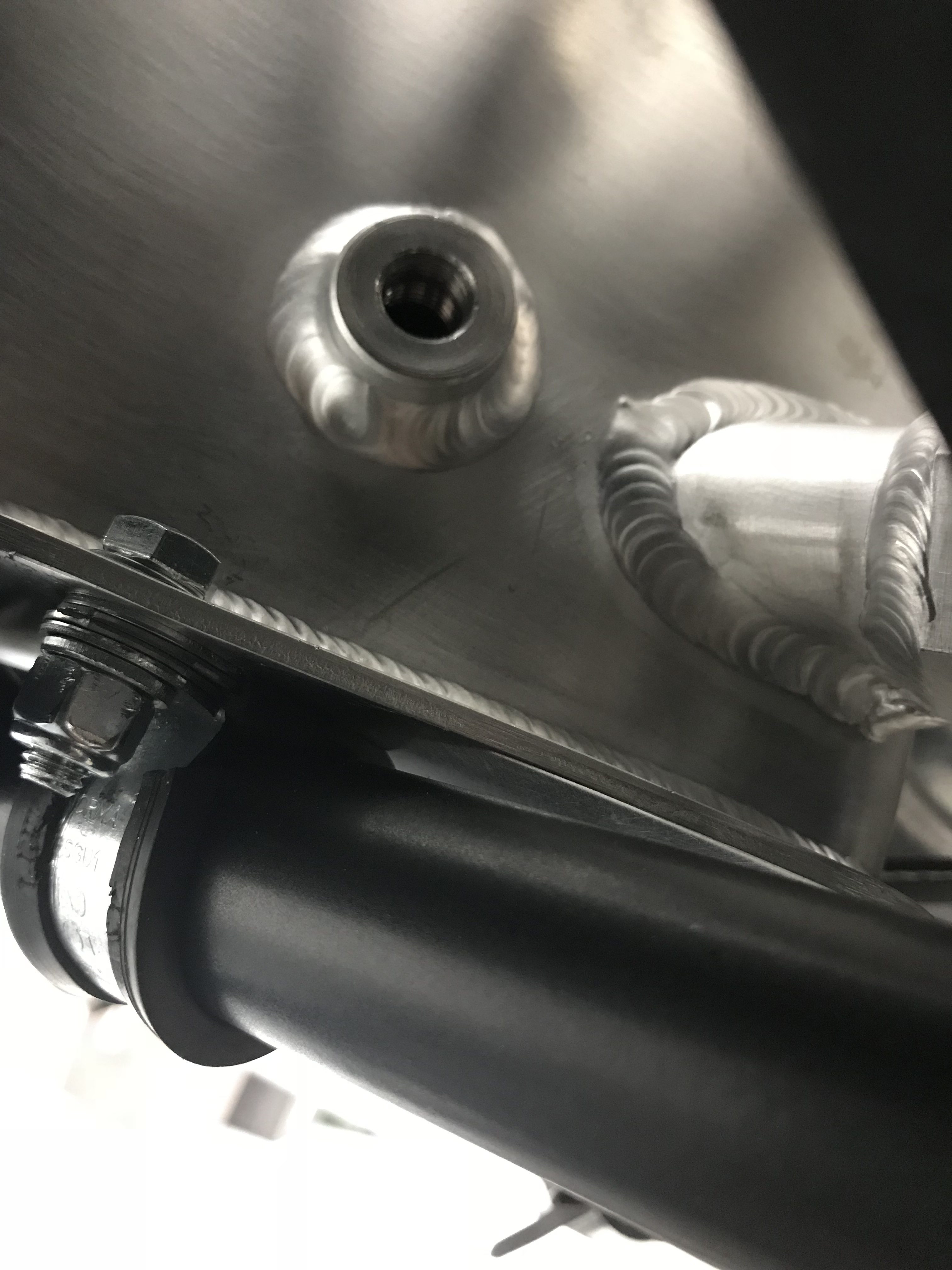
I’d read in the father and son blog that they had found a suitable bolt/set-screw and plugged the hole that way – with a copper washer no less. However, the thread seemed to be something other than a metric thread and I couldn’t find anything to fit from my collected junk (all essential, if my wife’s reading this!).
A quick email to Derek Howlett and he told me that this hole is used on the racing cars to fit an oil temperature sensor and is connected to the loom (connections which I don’t seem to have). He said that they usually stick a dummy sensor in there to plug the hole for non-race car installs.
Well that explains another conundrum… in one of the cardboard boxes there was a spare temperature sensor. I’d assumed this was accidentally included with my kit and was supposed to be used on the water circuit if I hadn’t already got a water sensor connected. Ahhh…. its the dummy sensor for the oil tank… I see.
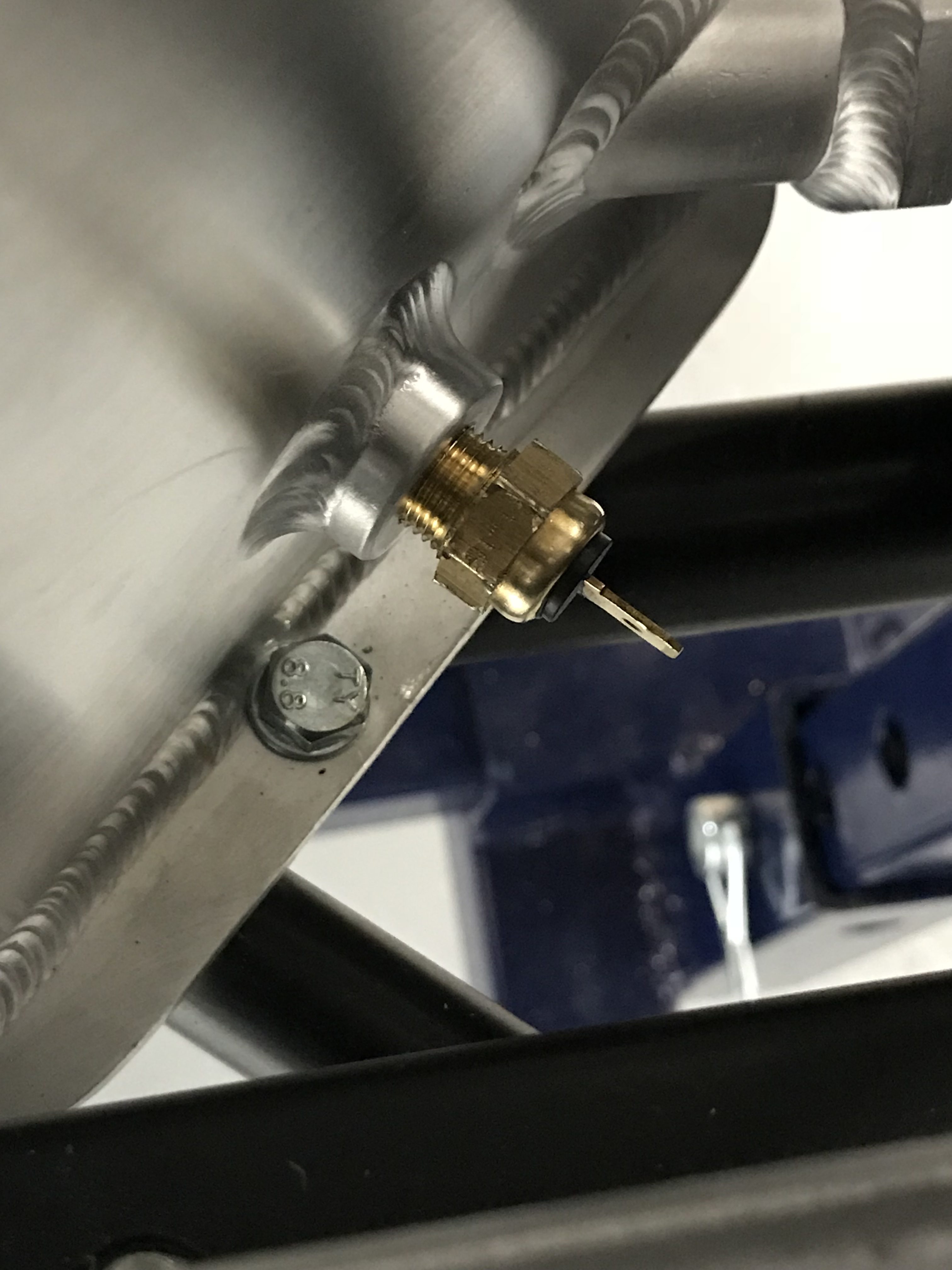
If I’d have thought about this some more then I would have also added some PTFE tape to the sensor threads just to make sure there was a good seal. I’d read somewhere that these sensors have a tapered threaded section and so don’t need the tape. Whatever… I was too eager and added the sensor in my haste to get a job done. By the time I remembered about using tape on the threads I had already added oil and there were no leaks from the sensor and so no harm done (for the moment).
Reroute 5/16″ Water Expansion Hose
Ok, so if you remember, I’d routed the 5/16″ water expansion hose as per the manual – from the expansion bottle, round the LHS (cold) side of the engine and then back around the back of the engine into a connection on the rear RHS of the cylinder block. This route didn’t take up all of the 5/16 hose but nearly all of it.
All the other builds I’d seen have taken this hose straight across the top of the primaries and cable tied it (if you’re lucky – on some builds I’ve seen it just dangles) to the rear cylinder head oil breather pipe.
I’d decided at this point that I was going to need the spare pipe that could be liberated by routing the 5/16 hose over the primaries – the spare is used to shroud the braided clutch hose and the braided brake hose at the rear of the car.
However, on the 5/16th pipe, I don’t just like using cable ties to lock things down. I know I’m going to have to do a lot of that later when I tidy up the engine bay, but it wrankles. So, I came up with a scheme to use two pairs of p-clips to attach the 5/16 hose to the oil breather pipe. It seemed to work out well, but we’ll see what happens at PBC and IVA – I’m a little nervous of this one.
[ A paragraph will appear here if it gets changed at either PBC or IVA – update from the future… it didn’t]
Handbrake Cable
This should have been a simple job… but… it wasn’t. I tried to do it late one night and clearly I wasn’t firing on all four cylinders.
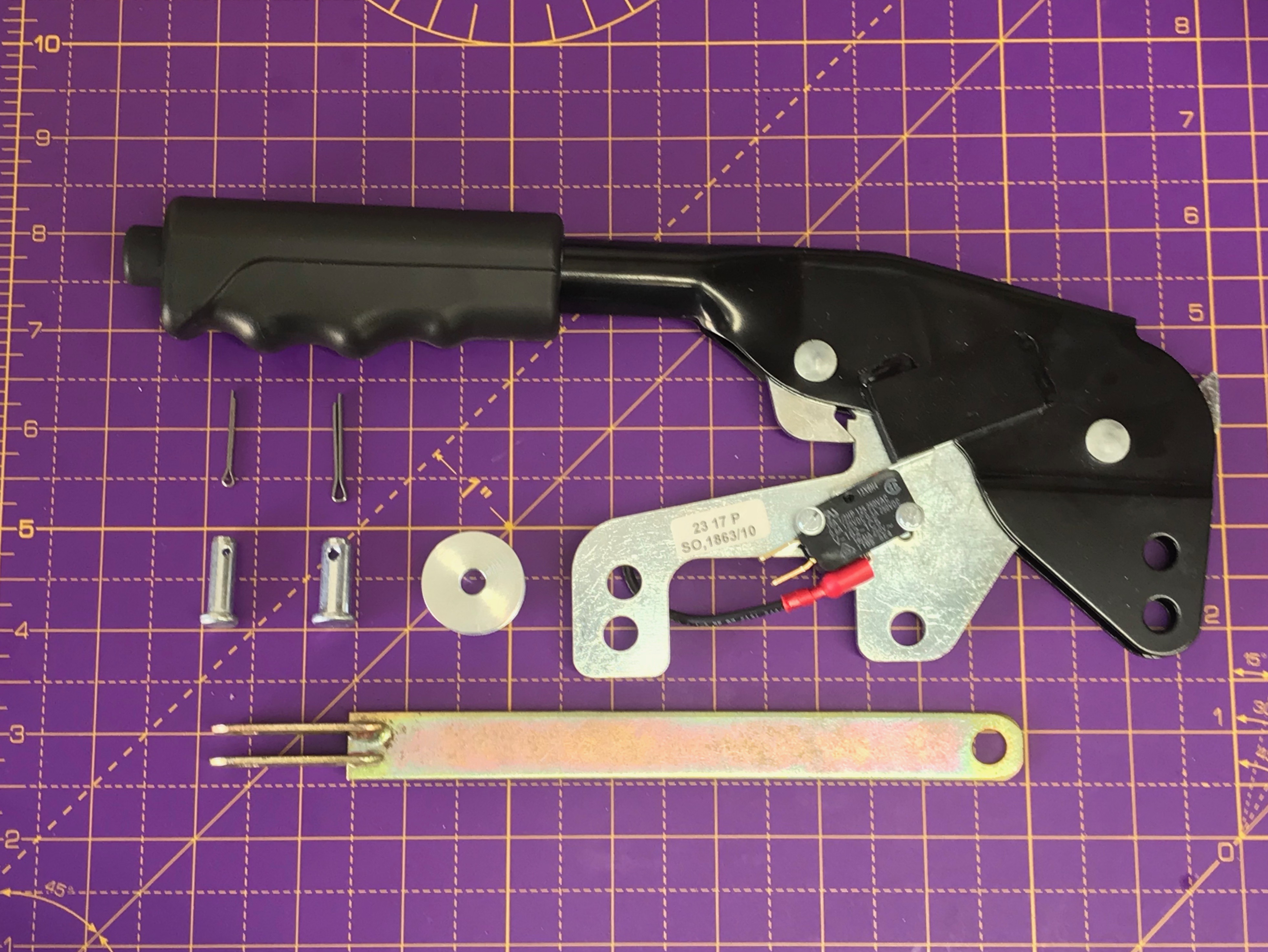
The handbrake cable is one long cable housed in a spiral metal sheath. There are hooks at each end where the cable hooks onto the rear callipers and there’s a break in the sheath in the middle where the inner cable loops around a pulley attached to the handbrake lever. The handbrake operates by pulling on the inner cable and therefore operating the rear callipers. While the inner cable is pulled by the handbrake lever, the outer cable remains stationary and is what is fixed to the chassis of the car. The outer cable is also there to protect the inner cable from abrasion – either from it rubbing as the suspension goes up and down, or from the handbrake being operated. I can also imagine that the outer sheath is there to protect a critical safety system (the brakes) from getting severed if a rock or debris, kicked up from the road, were to hit the cable. The connection from the handbrake lever to the cable is made with a clevis – which is essentially a u-shaped piece of metal (shaped like a tuning fork) and a wheel that can spin in the “u”. The wheel and handbrake lever are attached to the clevis with pins retaining pins and split turns holding them in place.
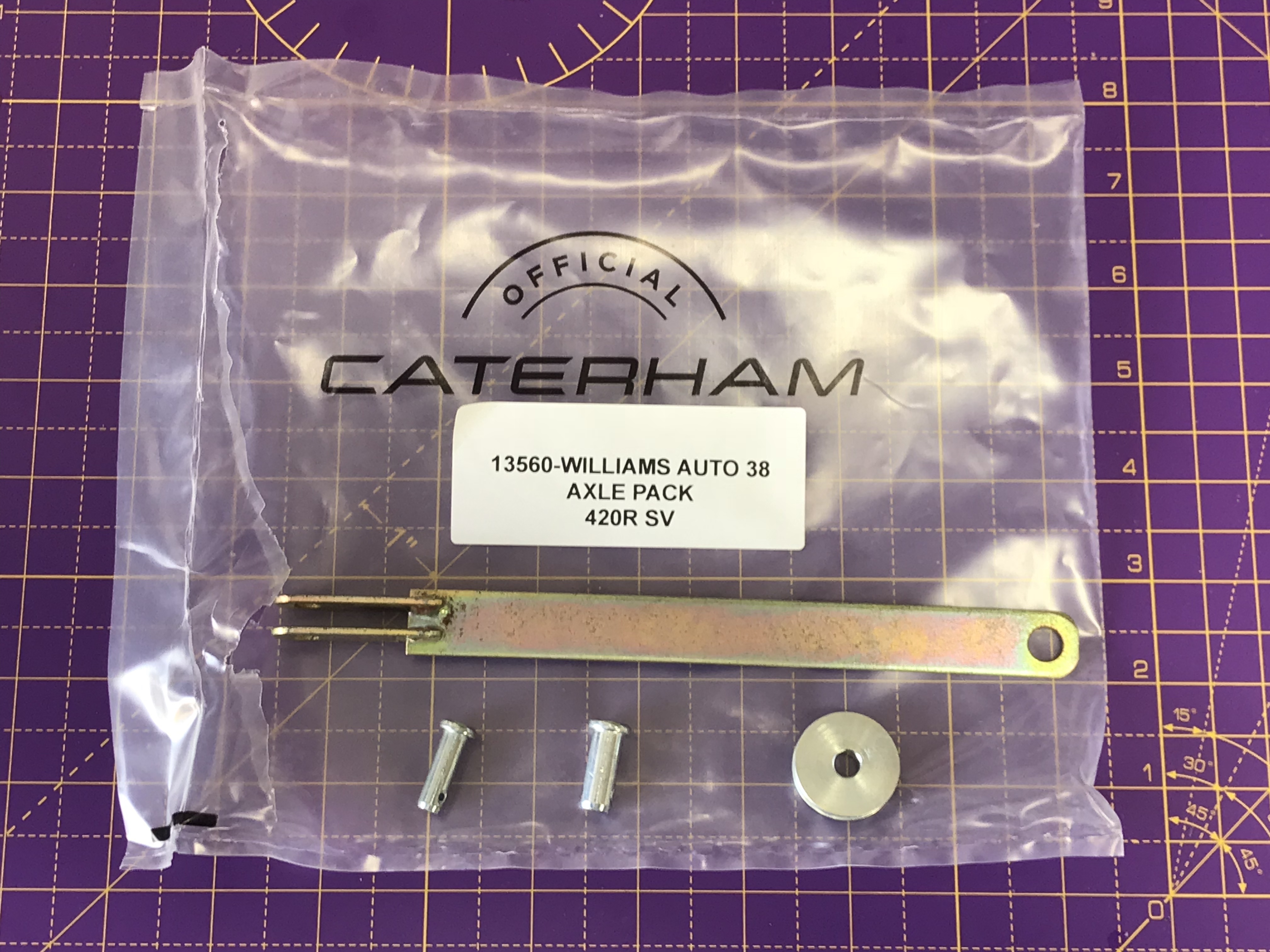
By the way… the clevis and wheels etc were in my poly bag marked “axle pack”. However, I found the split pins in the miscellaneous poly bag.
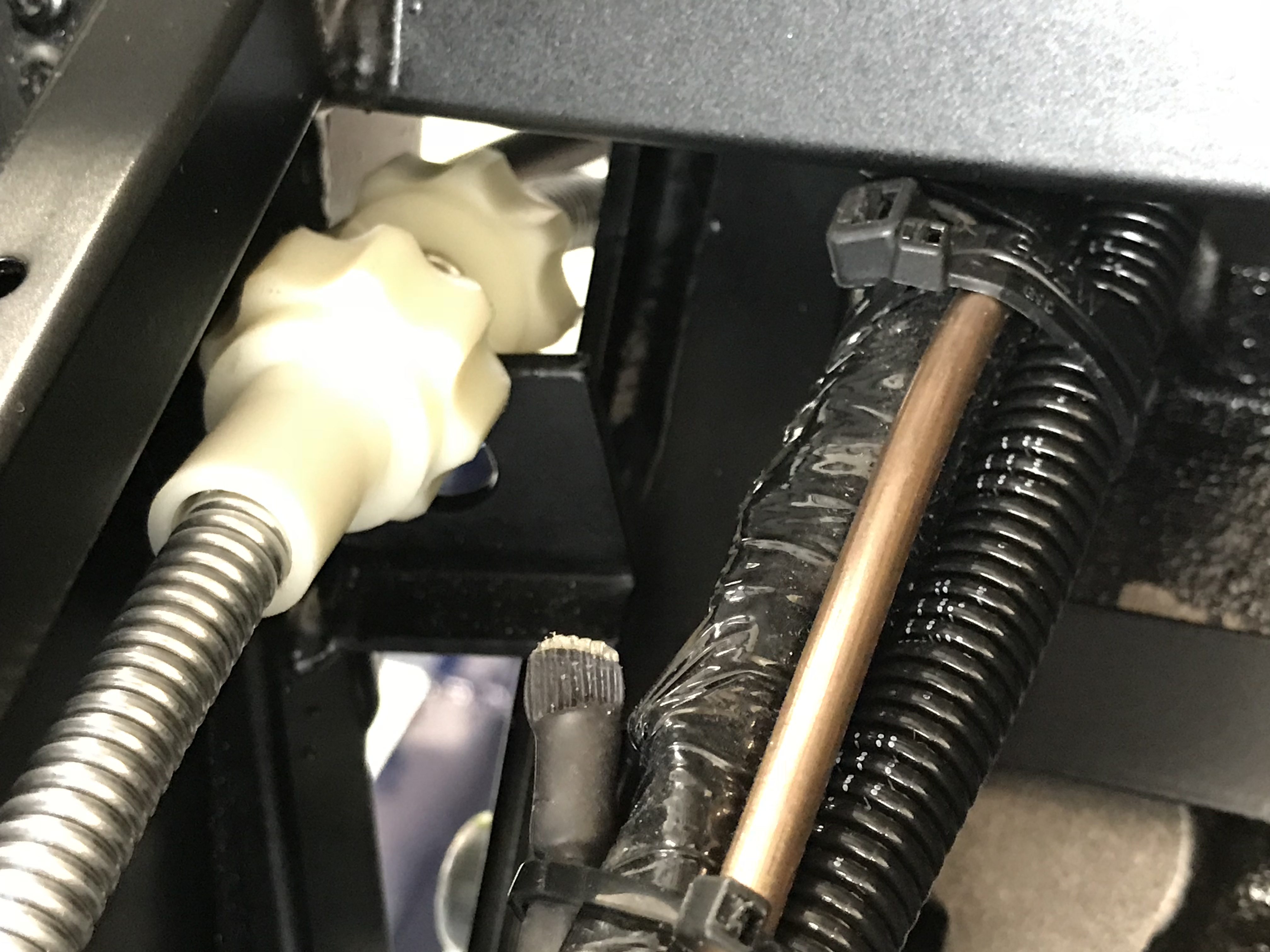
The bit that I got stuck on was where the outer part of the cable is retained in the chassis. On the LHS of the car there’s a yellow retaining plug that obviously sits in a clip in the transmission tunnel at the base of the rear firewall. There’s a similar clip location on the RHS of the transmission tunnel and I got it in my head that the handbrake adjustment screw should locate in there.
There’s also a retaining clip on the diff but I couldn’t see how to feed the handbrake cable into it. After a lot of pushing and shoving sort of got the RHS handbrake adjuster into the clip at the base of the firewall… but it didn’t seem right. Need to rethink…. hmmm.
Fluid for the Diff
So, one of the downsides of trying to fill the diff with fluid after installing the diff is that there’s not a great deal of room behind the diff – between the diff and the fuel tank.
My 14mm Allen keysocket wouldn’t fit in behind Diff with ratchet on it. The allen key set I had bought from Amazon some months ago had quite long shafts on them and the combined length of the allen key and socket wrench was about 106mm. It wouldn’t even fit into the hex bolt on the back of the diff. I could grind the 14mm allen key down in length but I’d rather have kept it intact. I asked two neighbours including Pete, the Lotus guy…. neither had anything bigger than 12mm.
So, another trip to Halfords… Which was fruitless…! Halfords had some expensive socket sets that looked like they had a shortish 14mm allen key but I had one already that would be a lot cheaper just to modify. I also thought I’d pick up some spare Diff fluid while I was there along with some hose and a funnel to fill the Diff with. I failed… no allen key, hose and diff fluid but I did find some cheap funnels at B&Q.
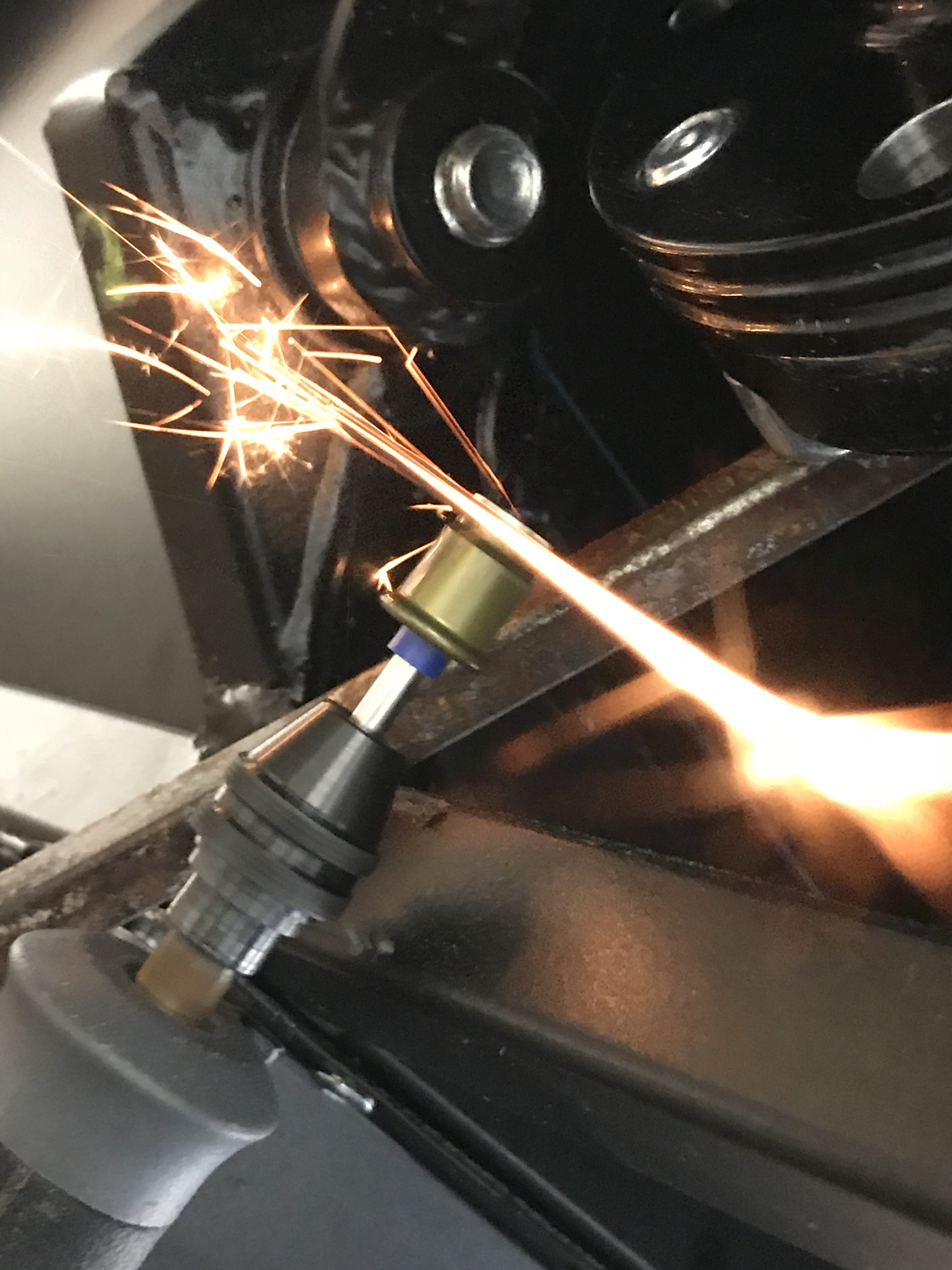
So, nothing for it but to cut off the end of the 14mm I already had. I started with a “re” (reciprocating) saw but finished with a metal cutting disc on a Dremel. I cut about 16mm off the end of the key I had.
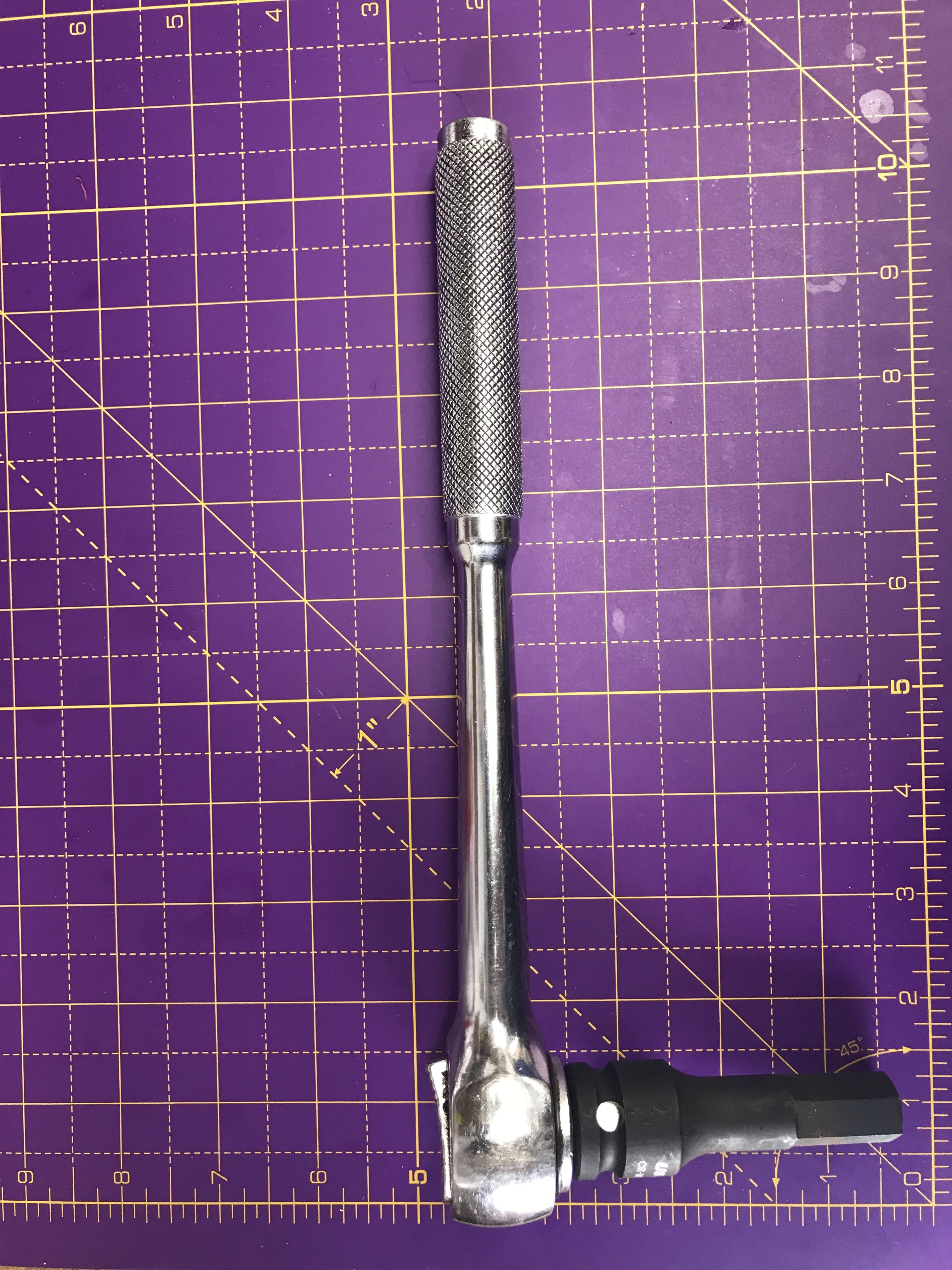
On my car there is ~105mm between the front of the petrol tank and the rear of the diff casing. Allowing for the 12mm depth of the diff drain plug you need your Allen key to be sticking out of the drain plug by no more than around 90mm – including any socket ratchet etc.
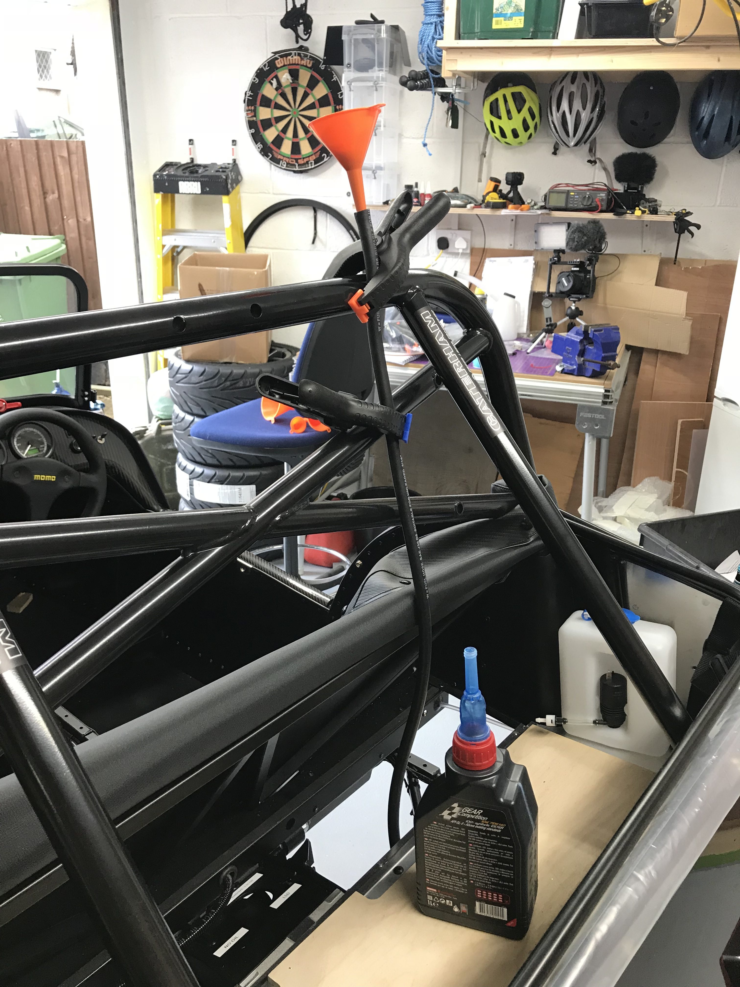
Filling the Diff
I tried to find some plastic piping while I was out at Halfords – even went into B&Q. I found some cheap funnels that were cleaner and less unwieldy than the one I had but no tubing.
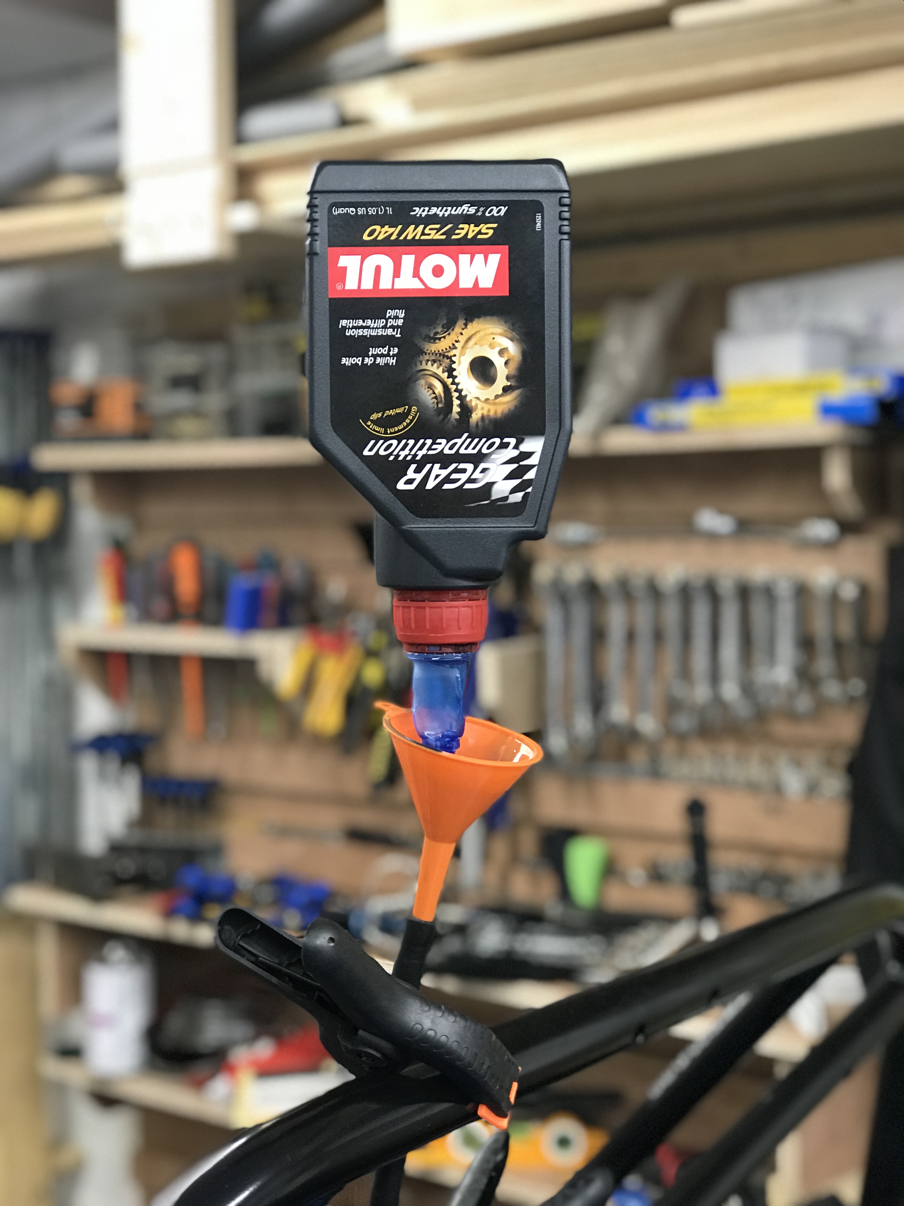
So, when I got home I decided I’d use the spare length of 5/16th fuel line hose that Derek had sent me for the water expansion bottle – this spare length of hose came about from routing the water expansion bottle over the hot side of the engine instead of around the cold side (see above). The two future uses I had for this spare tube were not going to be taking fluids and I guessed that whatever “synthetic differential fluid” is made of it wouldn’t be a problem to fuel hose.
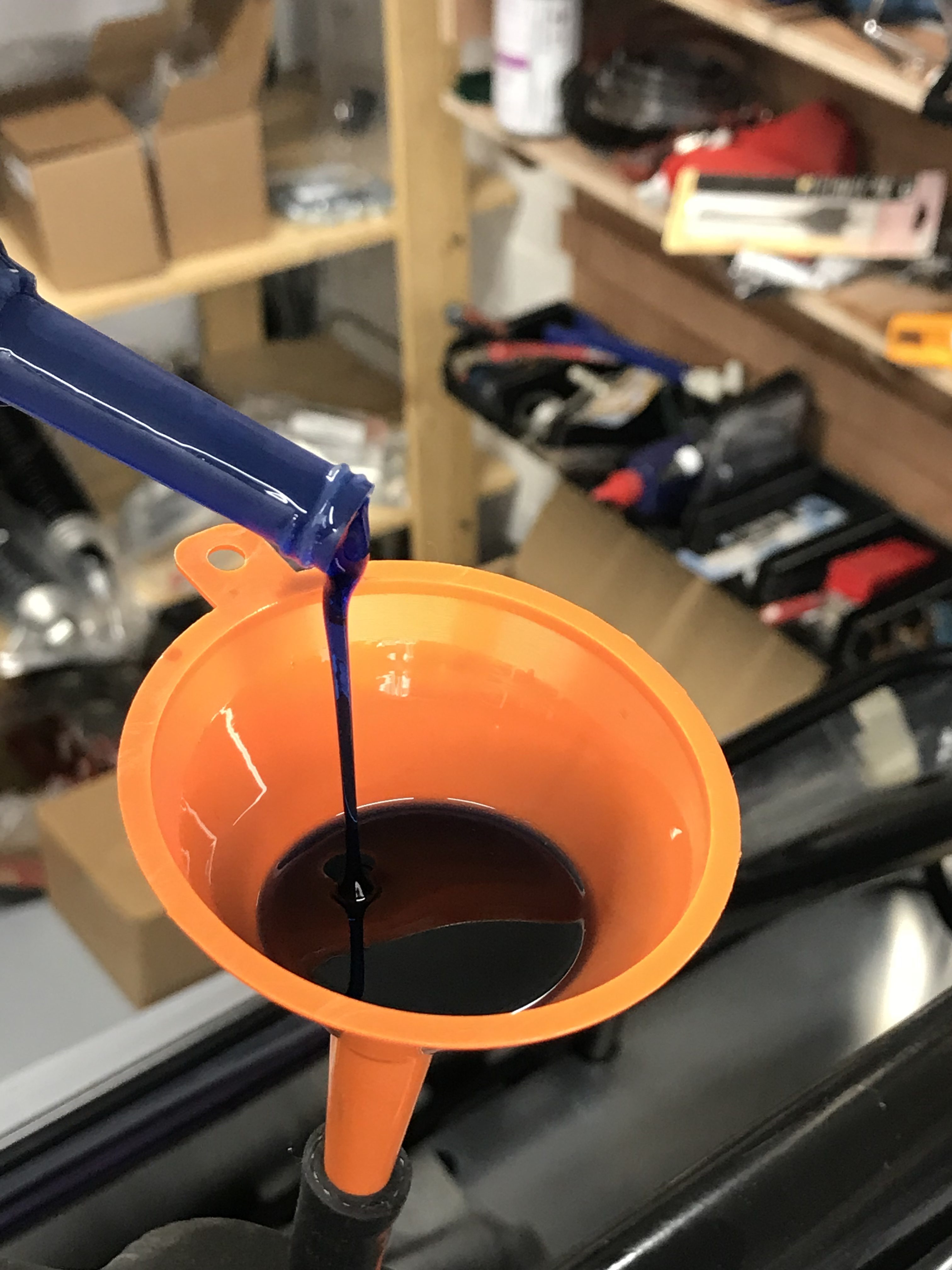
I set up the funnel and tube and started to poor. The funnel I chose was a little small but it fitted into the hose better than the larger ones so I had to spend more time filling but it probably wasn’t much slower.
The manual talks about filling the diff with 1.1L of oil. I presume that if the last 100ml was a problem then Caterham would have actually supplied 1.1L instead of the 1L container. I’ll try and remember to confirm that with Derek when I next find a reason to email him.
After the diff had taken the whole 1L I left it for half and hour or so for all the dregs of the fluid to run down the hose. It’s better to be in the diff than washed out and wasted.
A “little-finger” test (that’s using my little finger to test the fluid level and not meant to imply that the test was little) seemed to show the fluid level to be a few millimetres below the plug hole…. that’ll do for the moment.
According to the container, the fluid contains olefin sulfide and alkyl amine. The bottle warns that this can produce an allergic reaction. I had no problem with it on my skin, though I was carful not to get too much splashed around. However, filling the diff sent up a very strong smell of rotten eggs, given off from the sulphur content and it made me nauseous. I’m not sure its creating hydrogen sulphide, but it does smell like it.
When I was done I washed the fuel hose out with some universal solvent (a.k.a petrol) which seemed to do the trick at flushing the hose.
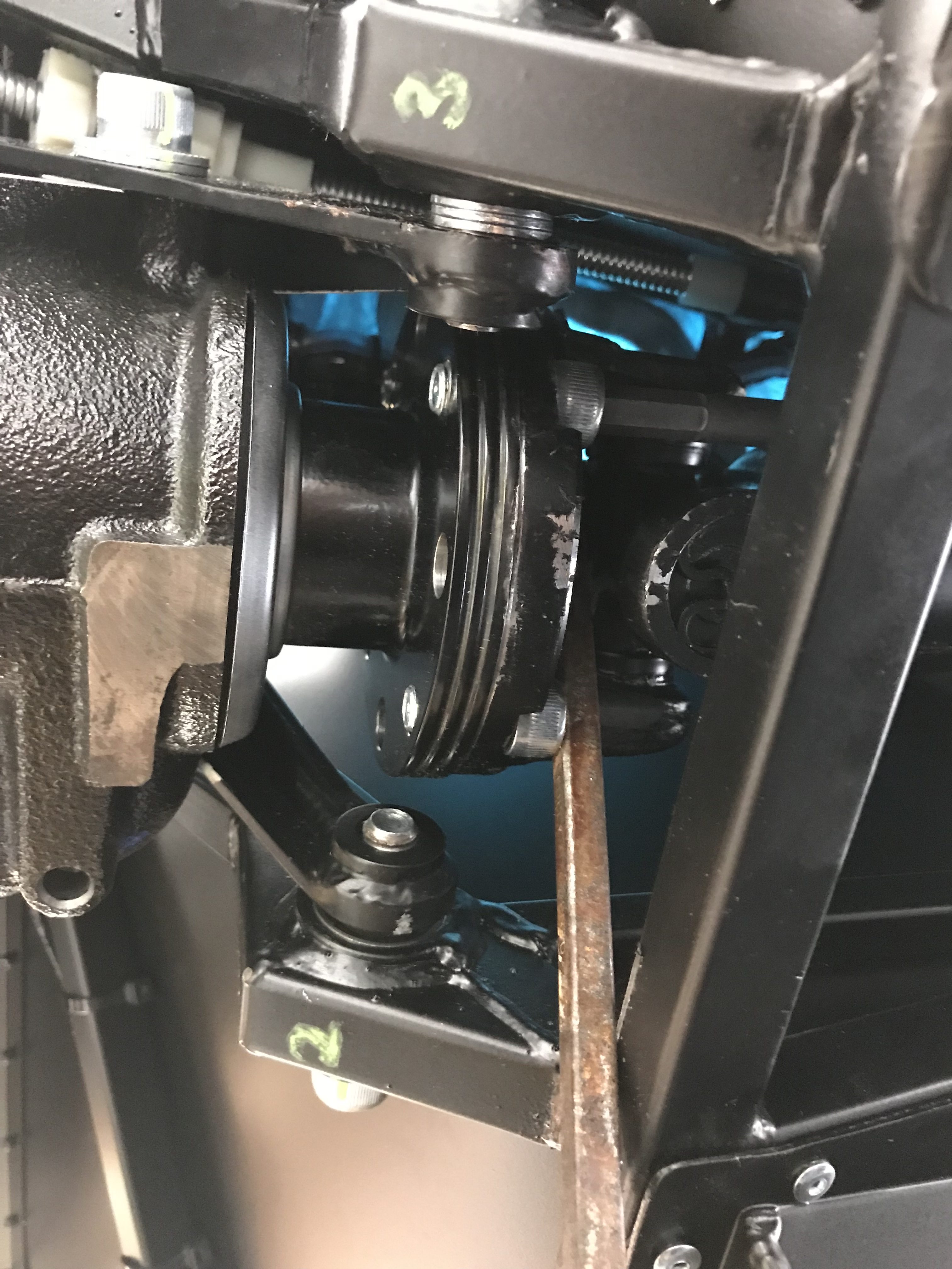
Propshaft Bolts
Ok. so today was not going to plan. What with the handbrake cable and now the propshaft bolts… things weren’t going as smoothly as I’d planned.
The propshaft bolts simply bolt through a flange on the back of the prop-shaft and into threaded holes on the front of the differential. You use some loctite to make sure they don’t come out.
However, as you turn these bolts, so does the propshaft. I tried putting the car into gear but the gearbox just didn’t seem to want to engage a gear. The only gear that went in was 5th and that jumped out as soon as I turned the prop. I’ll have to take a look at that at another time too.
I also tried jamming a screwdriver into the universal joint at the rear of the prop-shaft and tightening the bolt up against an opposite force on the screwdriver. But the screwdriver kept slipping… and… then… … … it jammed.
Bummer!
I was using the mankiest (that’s a good british word), crappiest, big screwdriver I had. It has a square shaft that’s great for getting a spanner on when a screw won’t shift, but in this instance the square section resolutely jammed itself between a chassis rail and the inner workings of the universal joint.
Bugger!
I tried all sorts of to-ing and fro-ing of the screwdriver and propshaft. But to no avail. The screwdriver wasn’t coming out.
After a cup of tea and a think… there was nothing for it. I was going to have to cut the screwdriver out.
Out with the dremel and 5 minutes later I had a much shorter screwdriver.


Ok, that’s enough of that… I submit… I’ll take a look at the propshaft bolts another day.
By the way, if I can get to the point where I actually have the bolts installed, I’m using Loctite 270, high strength, for the propshaft. Can’t be too careful about the propshaft bolts coming out!

Drive Shafts
Next up is fitting the drive shafts. Simple job. They are handed and drop straight into the diff once the red plastic stoppers have been removed from the diff. They didn’t seem to go fully home but I’ll take a look at that in the morning.

That wasn’t quite the end of a relatively long day, but I’ll cover the De Dion tube in one go in the next post. Some success, some failure. More of the former tomorrow I hope.

Leave a Comment