

Whoa boy… you’re getting ahead of yourself!
At the end of the last post I said it was time to start thinking about starting the car. I “could”… but… I’m still unhappy about putting fluids in the car and I clearly hadn’t quadruple checked the quadruple checking I’d been doing!… I need oil and water in the engine circuits to start it and I still want to think about the pipe routing some more, and, and and…
… Hold you’re horses, we’re nowhere near starting the engine!
So… on to the interior instead. Phew! That was close!
Scuttle Trim
Start the day with something simple.
I’ll call this trim “interior” even though it feels very exposed but the scuttle trim technically sits inside the car once you have the hood and doors in place.
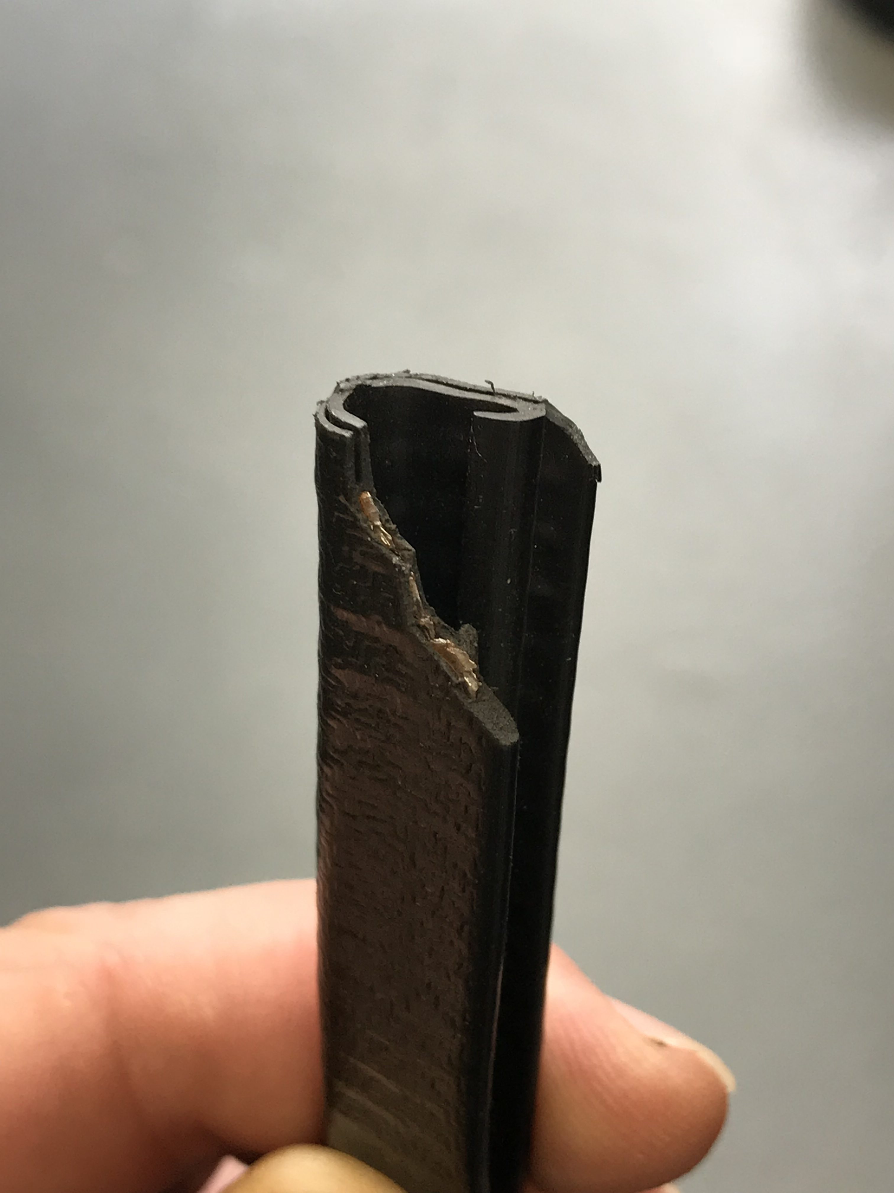
The scuttle trim is a “rubberised” u-shaped channel piece (see below) that has what looks like a squashed steel helix embedded in its construction. It looks similar to the smaller and more flexible IVA trim used elsewhere in the build, but is bigger and has the extra rigidity imposed by the steel insert.
This trim also gets used on the leading edge of the catalytic converter shroud and I’ve also seen it used on the lower LHS engine bay cross member to protect the lowest oil line from rubbing.
But back to the scuttle… The trim is placed on the rear edge of the scuttle, essentially inside the passenger compartment. The idea is that the scuttle bodywork edge is too sharp and the trim is needed in case you’re involved in an accident. The trim both softens the edge (mechanically) while increasing the bend radius at the same time.
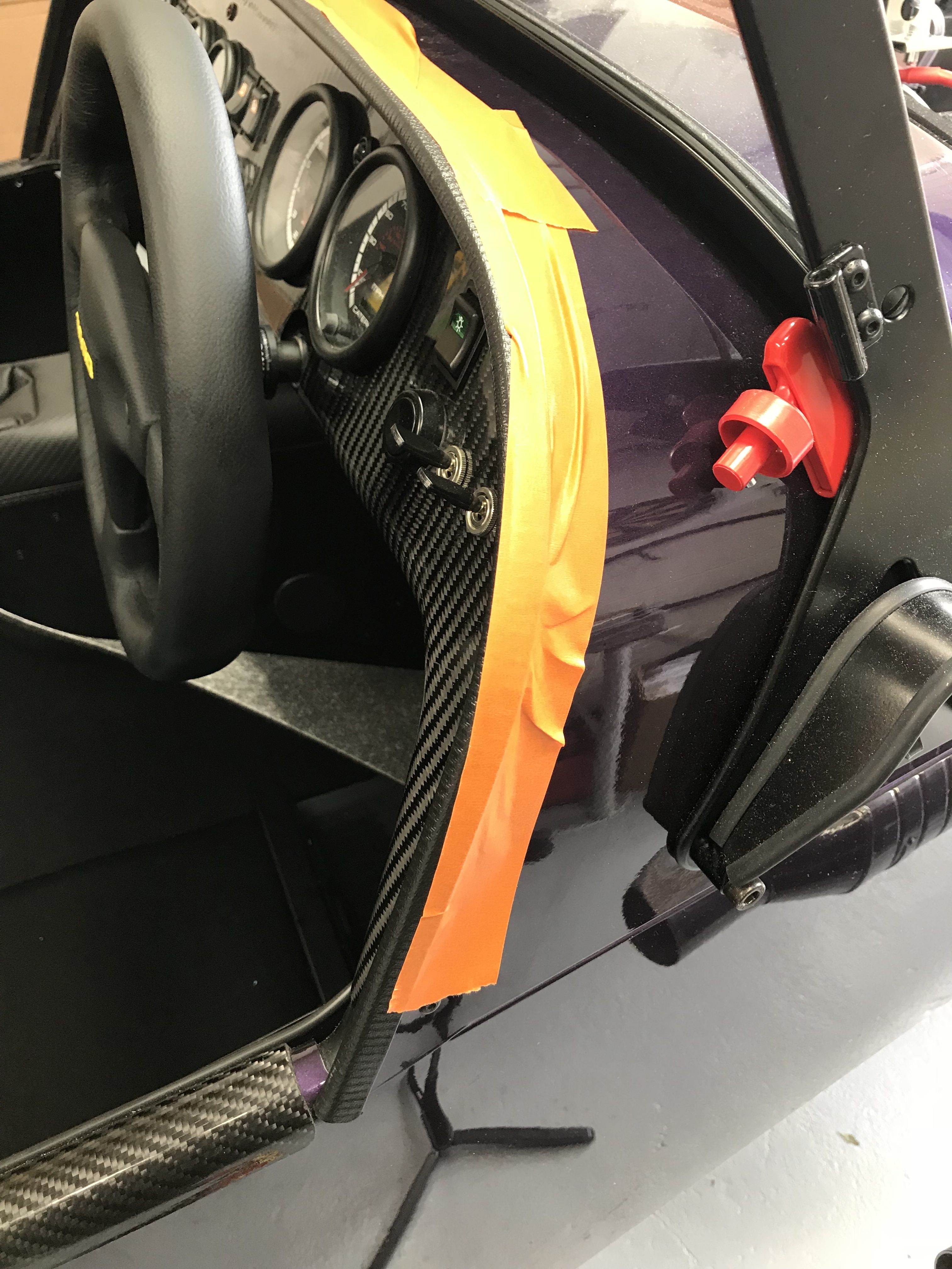
I chamfered both ends of the trim as I installed it, mainly so it looked better but also so the ends sat flush with the bodywork panels.
I tried to “cold” fit the trim initially. It wasn’t a cold day and I thought the trim felt pliable enough. However, as I fed the trim onto the scuttle it was just not going right.
So… out with a kettle, a bowl, and a steaming pool of hotness to heat up the trim.
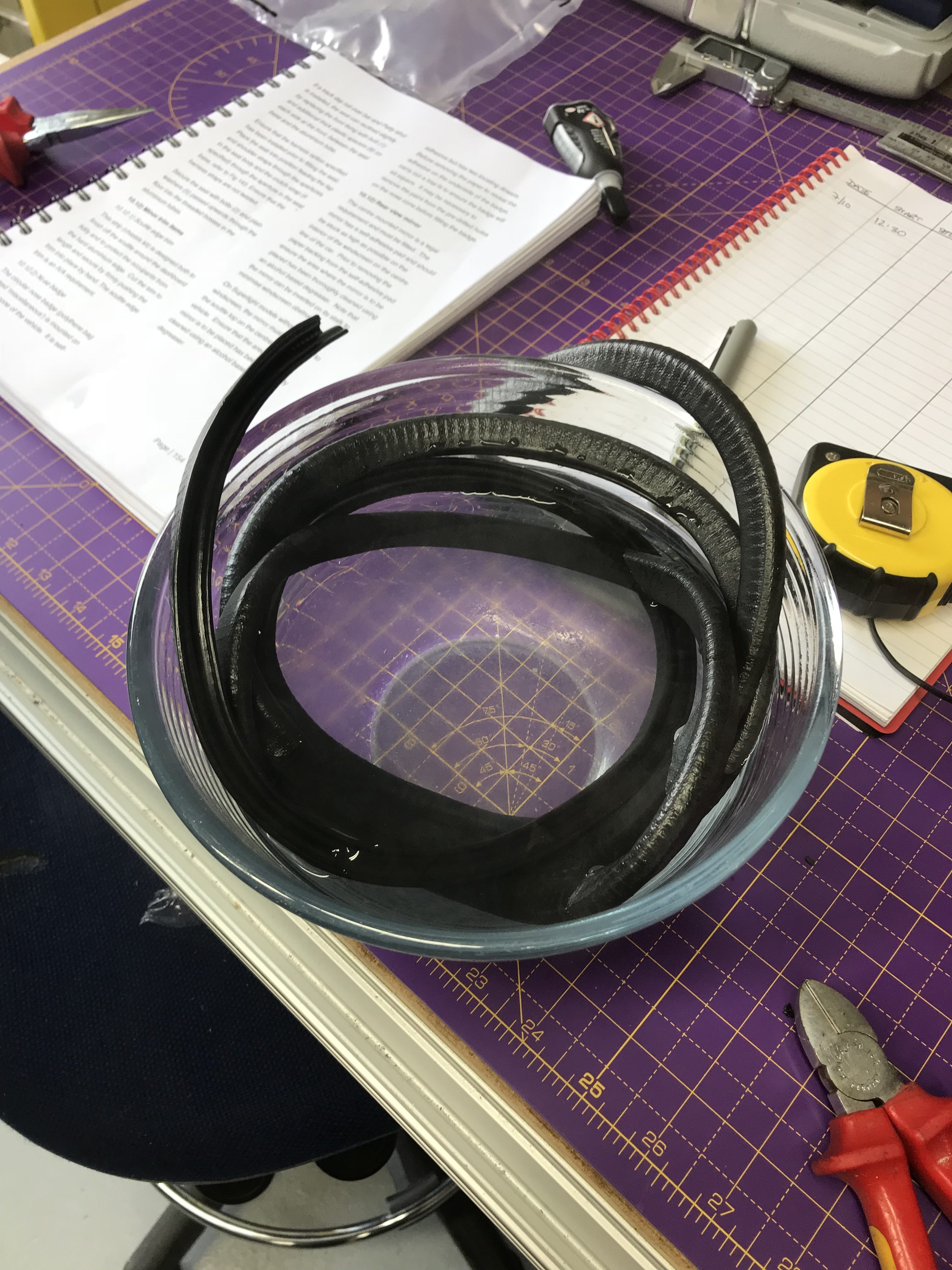
The heat made a bit of difference but not quite what I’d hoped for. The trim, as it was applied, had a tendency not to sit flush with the scuttle bodywork as it went around the tighter radiuses at the sides of the car. I’d hoped that heating up the trim would allow it to sit flatter on the scuttle but it didn’t make a material difference. The steel work inside the trim was clearly keeping its shape more than I’d hoped.
Knee Trim Panels
I wasn’t looking forward to this bit. Plenty of others have commented on what a pain they are to fit.
On our car a lot of the interior paneling had been done. As well as fitting all of the hood “poppers” into the body work, the sill protectors and elbow rests had been installed. This meant that most of the rivets along the outer sides of the passenger compartment had been fitted. The riveting stopped just before the point where the sill meets the scuttle and means you are still required to fit the knee trim panels under the dash.
Caterham clearly thought that while the knee trim panels are a pain, they are not something that people screw up enough to cost Caterham money. My theory on why they now fit the hood is that it involves drilling a lot of holes into the bodywork for the poppers and I suspect that people may sometimes screw this step up and ask Caterham to then fix the misplaced holes created in the body work… very expensive for someone.
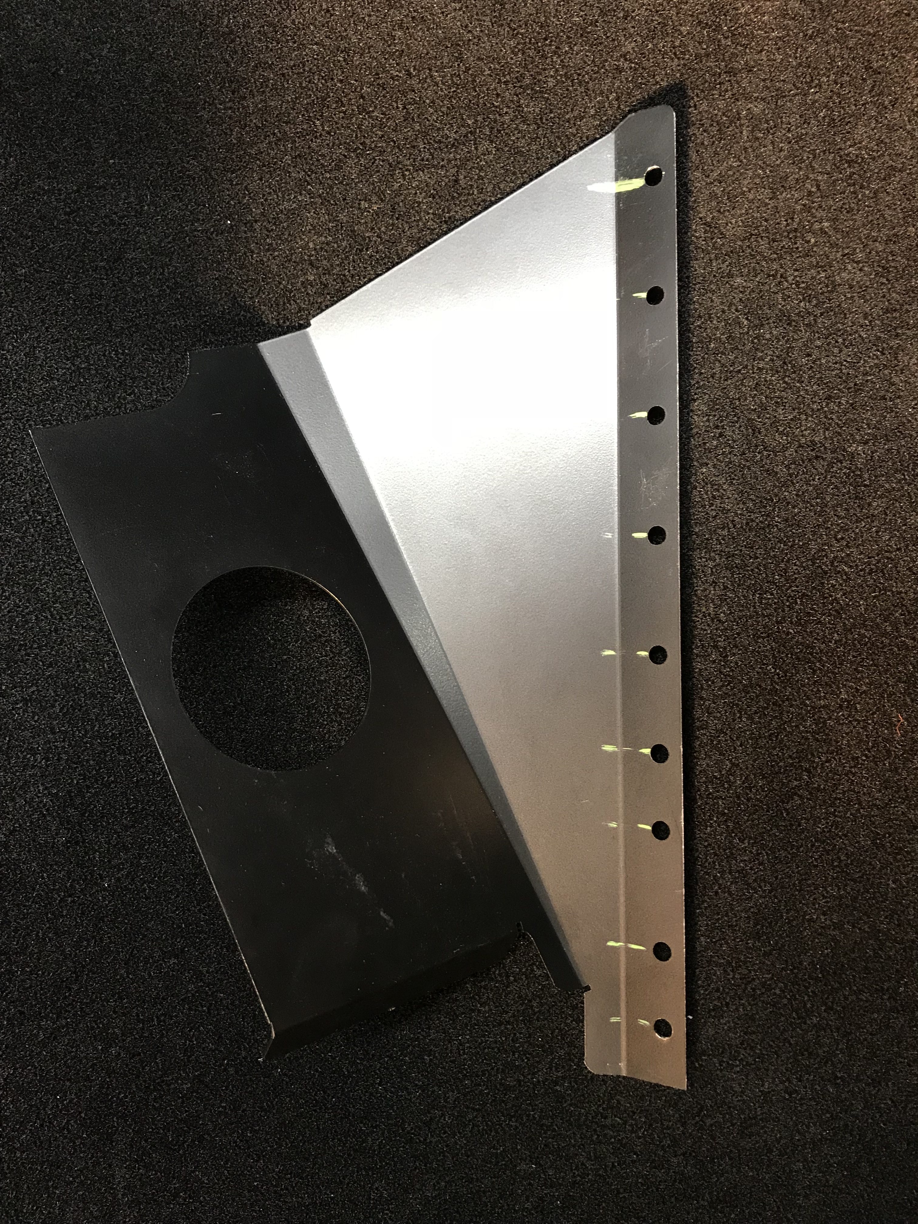
So, the knee trim panels fit under the dashboard on the outside of the passenger compartment – one trim panel for both drivers and passengers side.
The trim panels are supposed to stop your knees from being hurt in an accident. If they weren’t there then you flailing knees might impact a bunch of electronics and wiring up under the dash.
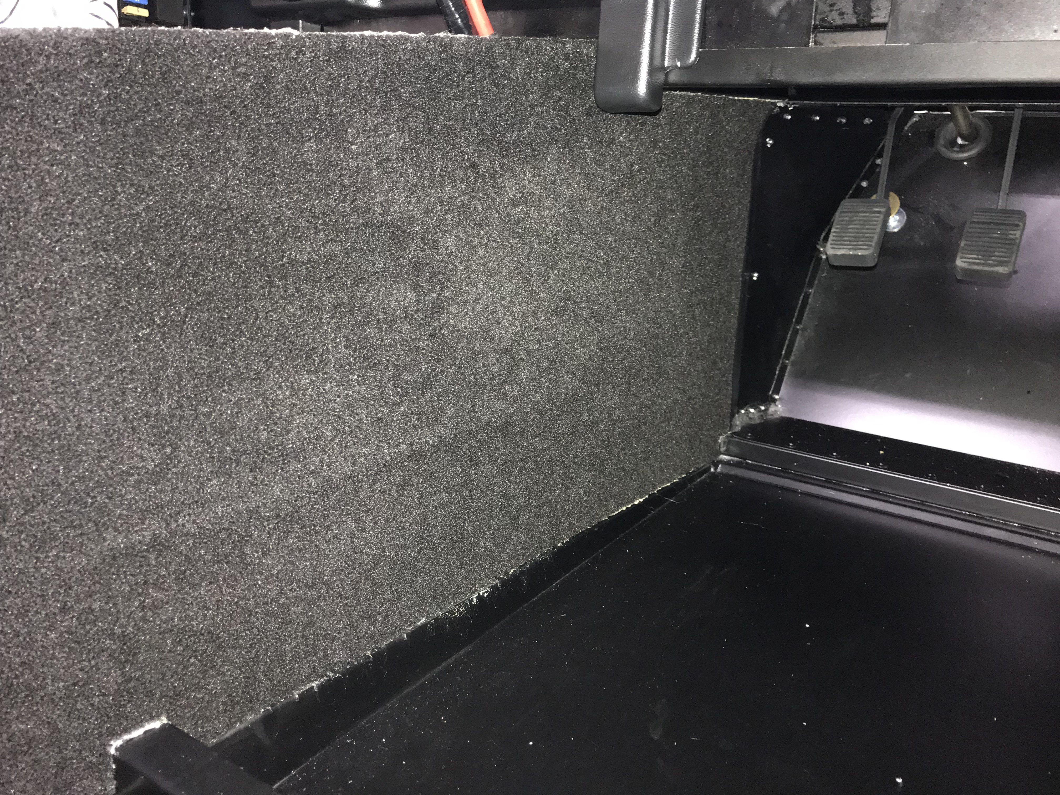
These trim panel installations require you to locate the trim panel against the back edge of the firewall, in-between the inside trim panels running down the footwell, the scuttle and then sandwich some rubber piping in-between all of this.
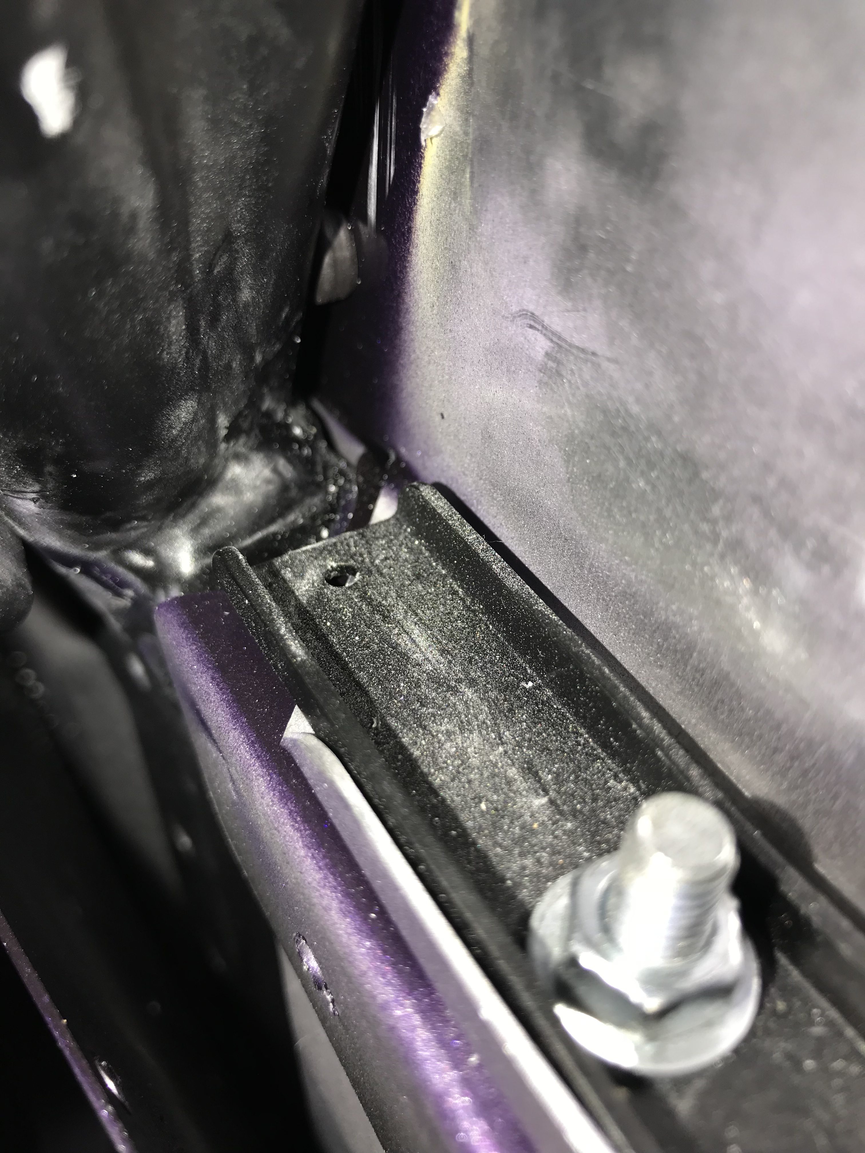
To boot… the trim panels are the wrong shape! At least that’s the conclusion I came to. I’ve heard that some people stuff the panel in place and then drill out new rivet holes to accommodate the position the panel finds itself in. My solution was different. It looked to me as though the rear of the panel was fouling against the chassis at the point the scuttle meets the sill. There’s too much metal in the chassis at this point and the trim panel needed to be cut to accommodate the shape of the chassis.
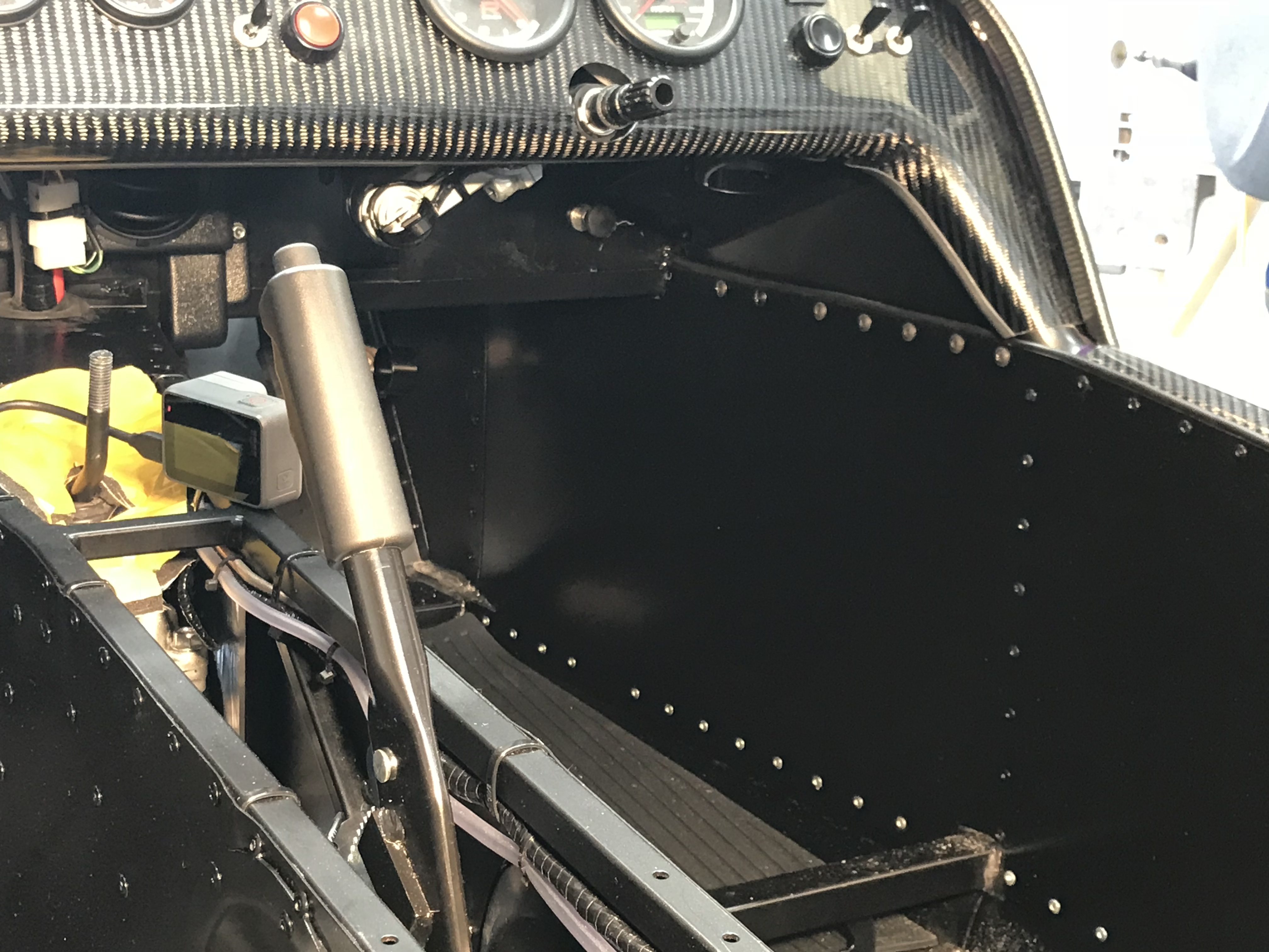
It is awkward getting into the footwells to see what’s going on in that area. There’s not much space and not well lit. I ended up putting an inspection lamp onto the transmission tunnel to give me enough light to see more of what was happening.
I also resorted to taking pictures of “up and back” into where the scuttle meets the sill.
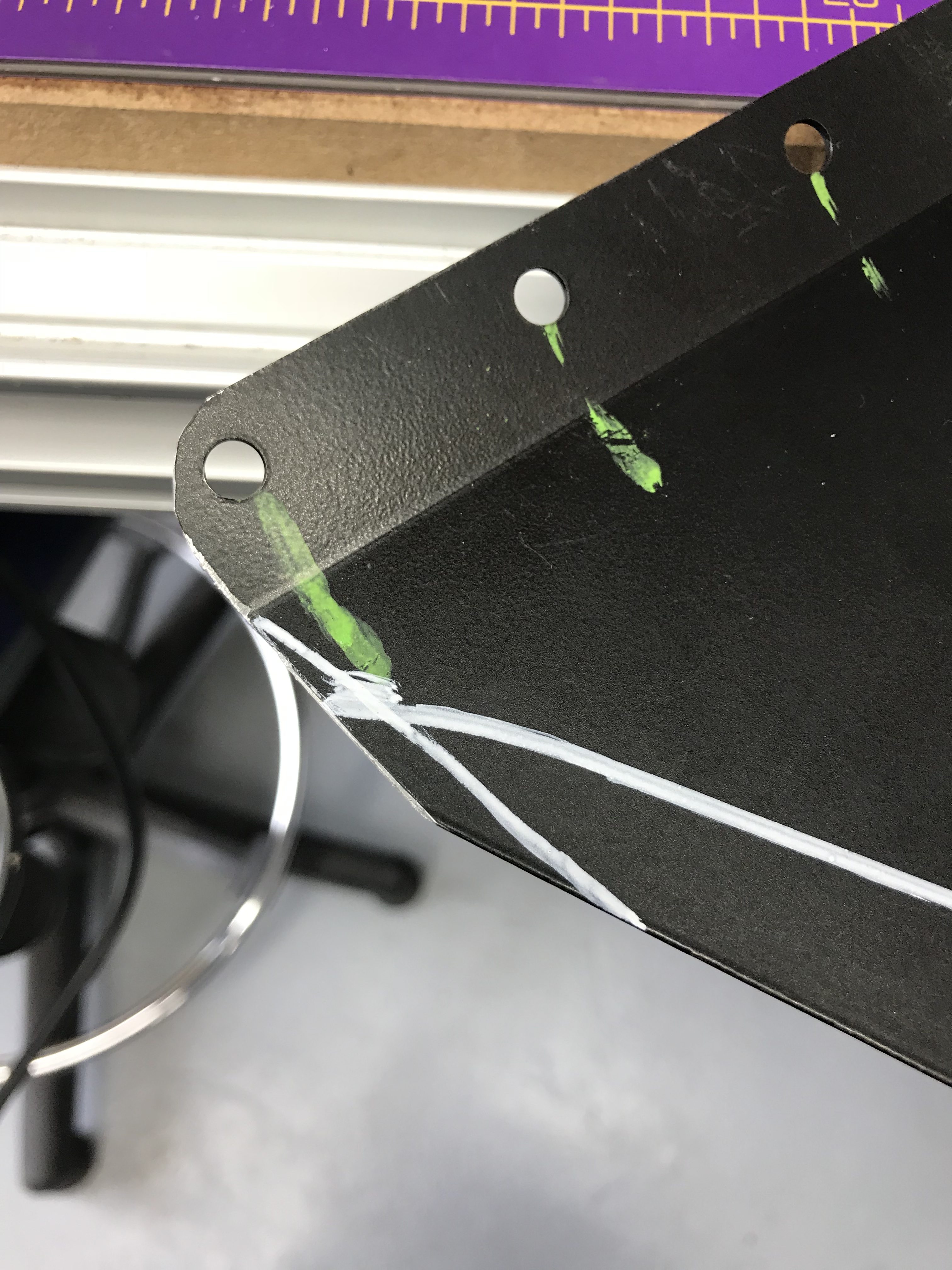
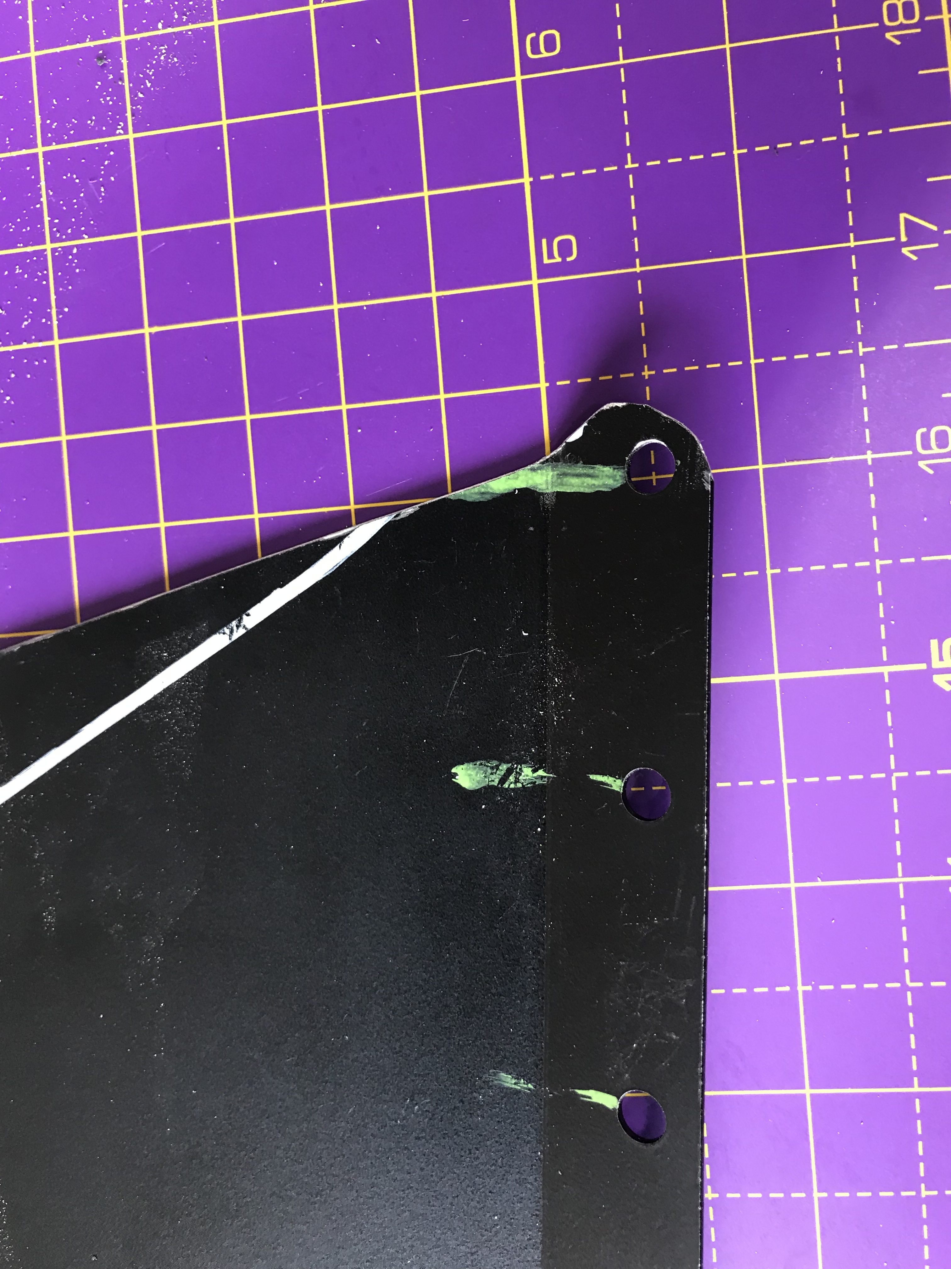
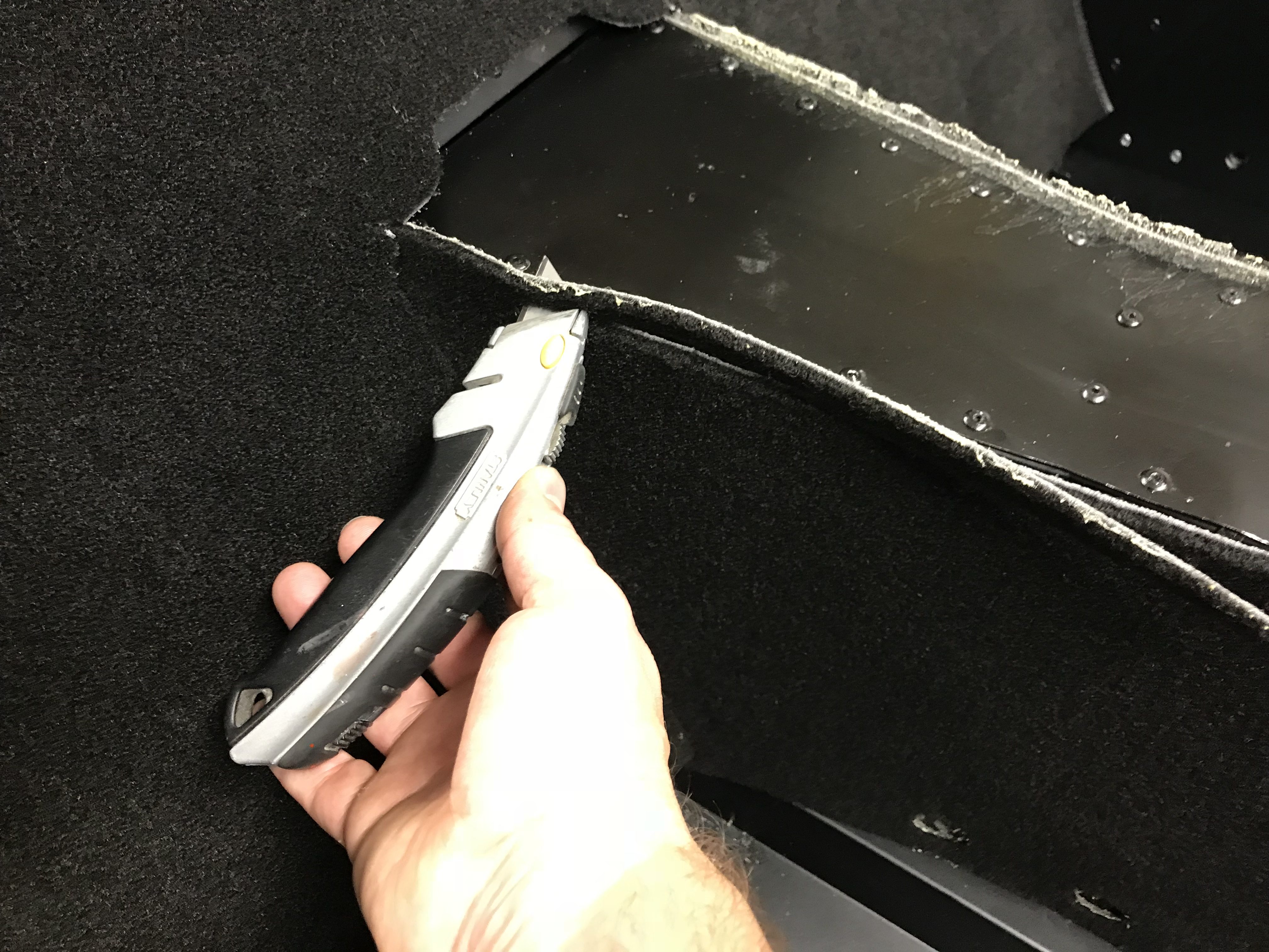
I found it useful to mark the positions of the existing rivet holes where I could see them when the trim panel was in place. That gave me a sense of how far I was “out” and how much I needed to trim from the panel.
Having spent at least half and hour getting my head around what was going on and potentially what needed to change, I marked up the trim with what I was going to cut. The following images show my successive attempts at cutting away at the trim.

Now that the trim was in place I could cut the holes in the “rubber” piping that fits between the two sets of panels.
Having got the trim panels to the right size, they need to be fixed. The trim panels themselves are fixed with self tapping screws but there are also rearward parts of the inside trim that also need to be riveted and where Caterham decided “enough is enough, we’ve done enough riveting on this car. Let the customer do the rest”.
I eventually got there. Though I probably spent at least a couple of hours on this task.
The knee trim is finally held in place with black self tapping screws. There are also large access holes in the panels that I presume are there to allow access to the back of the battery cutoff switch etc. Given that the panel is held in with self-tapping screws and not rivets, I would have thought it would be better to just remove the panel rather than attempt keyhole surgery through the access grommet… we’ll see about that when the time comes to tinker.
Could I have completed this task with just drilling out new rivet holes… probably. But I don’t think the panel would have sat “true” to where it was meant to go. I think there would have been gaps between the panel and the scuttle/chassis/firewall and my OCD attention to details that don’t really matter wouldn’t allow me to go with that! Sorry!
Carpets
Now onto something completely against the ethos of a Seven…. Carpets… in a Seven… sacrilege!
Well… sort of. I’m certainly not interested in carpets to make the interior more “plush”. And it’s not a bling thing either. I wanted carpets as an attempt at noise suppression. I hope to go on some reasonably long journeys in this car and I hope that significant people in my life might want to come with me. Reducing noise levels by a few dB sounded like a good idea to ease those discussions.
So, on with the first stage of getting the carpets in. I know today is not going to get them all installed but at least I can scope out what the whole thing is and to at least get the first pieces of carpet in place.
Ok… but hang on… the first carpet goes onto the firewall at the back of the passenger compartment, behind where the seats go. Hmmm. This piece of carpet has a “leatherette” trim piece that sits over the rear edge of the boot (trunk) and needs holes in it for the seat harnesses.
That means the first job is to remove the boot cover that Caterham had pre-installed.
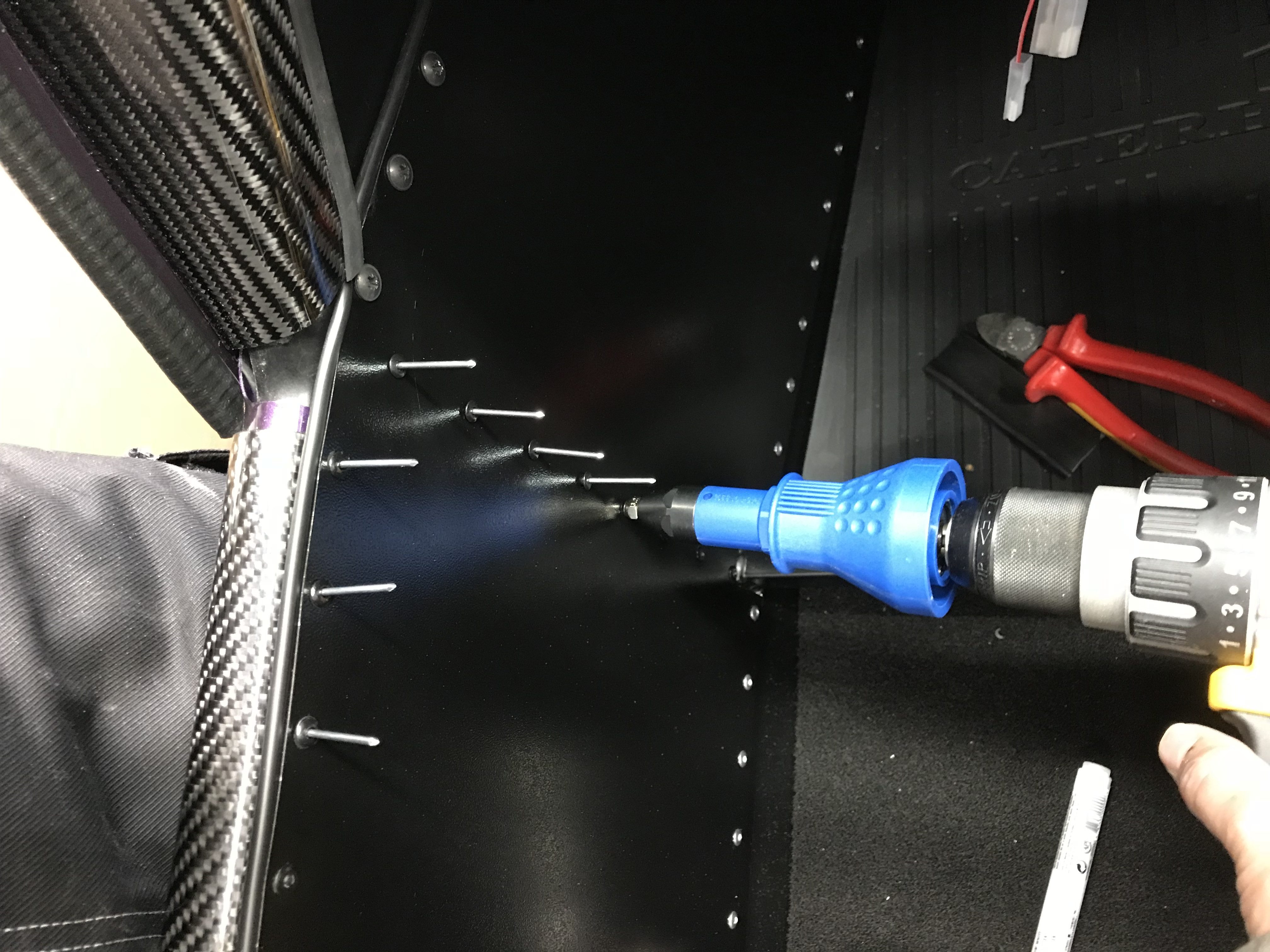
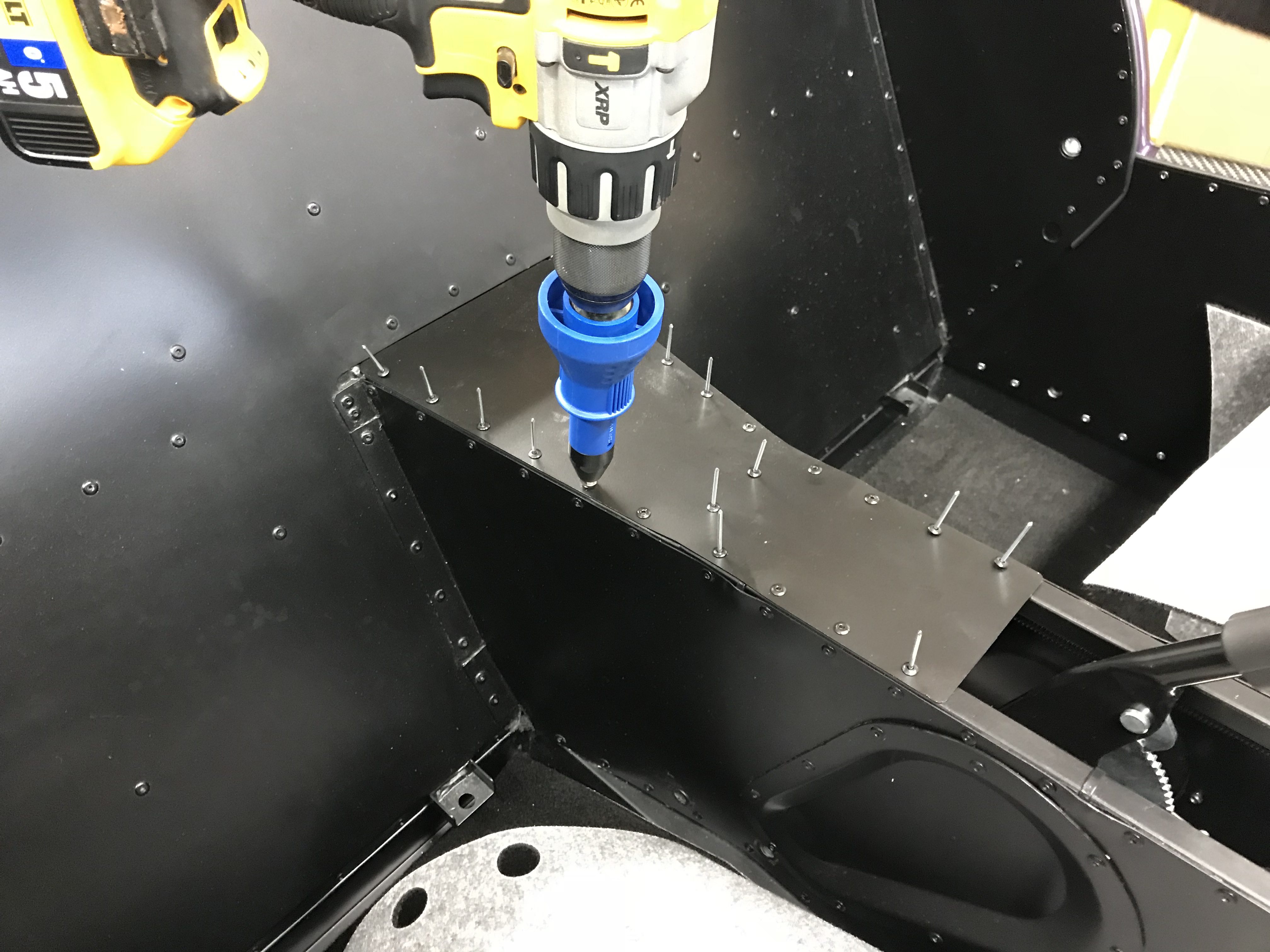
And because the carpet on the bulkhead also fits around the transmission tunnel, I also need to fit the trim panel that sits on top of, and at the rear of, the transmission tunnel. This is my first bit of serious riveting. The drill attachment made light work of installing the 20 or so rivets.
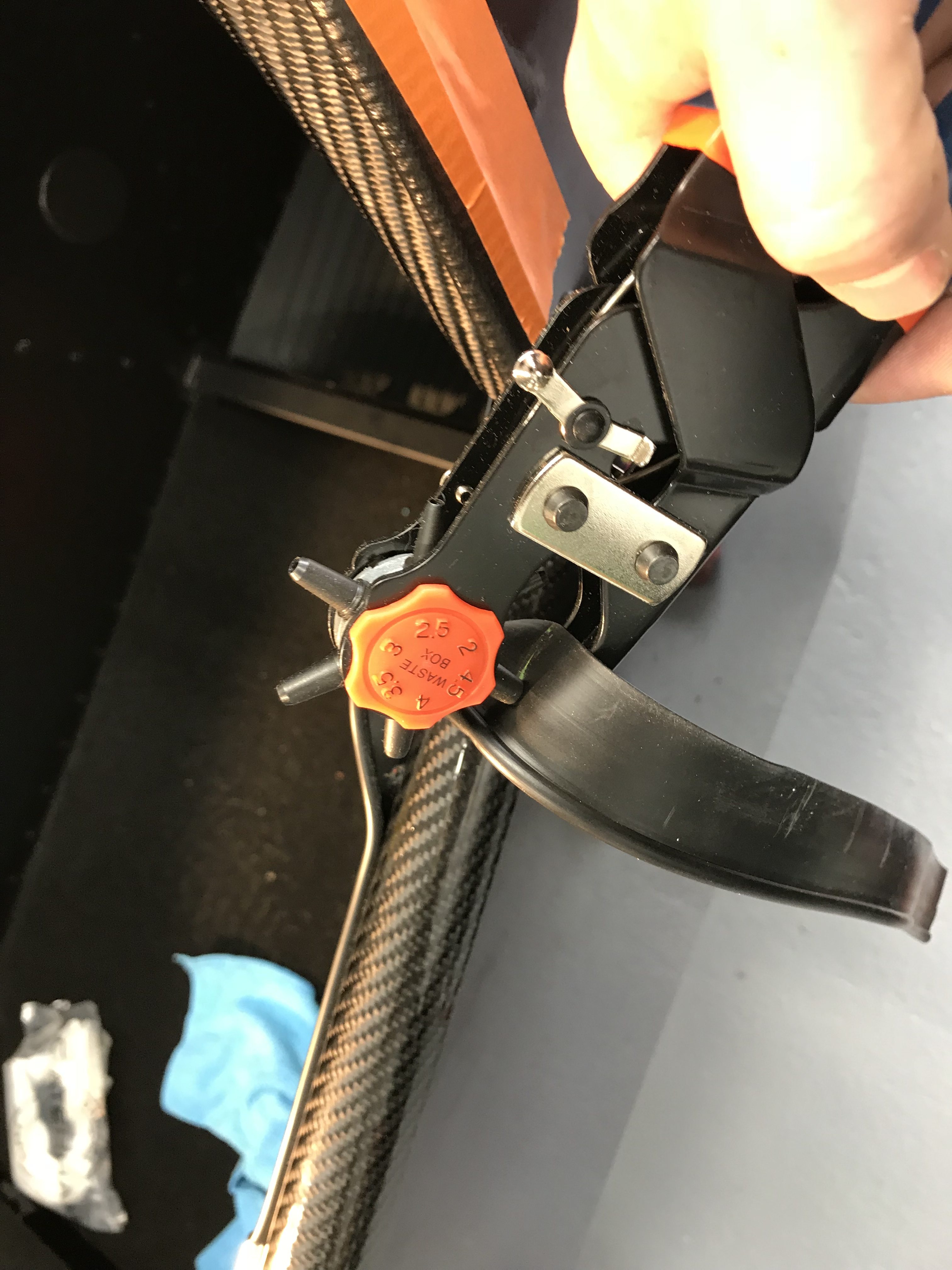
Once the transmission tunnel panel was in and the boot cover removed, I could properly turn my attention to the firewall carpet. As mentioned above there’s a leatherette piece on the top edge of the carpet. Holes need to be cut in this leatherette so that the seat harness bolts can be re-inserted. I spent a lot of time with spring clamps setting out the carpet/leatherette and figuring out where the holes should go. Once I was happy and had the holes marked out, I cut the holes with my punch set. I used an oversize punch just to make sure I had some wiggle room when attaching the carpet and had sticky glue everywhere – in the end I was able to put the carpet back in almost exactly the same place I had mocked it up to be in.
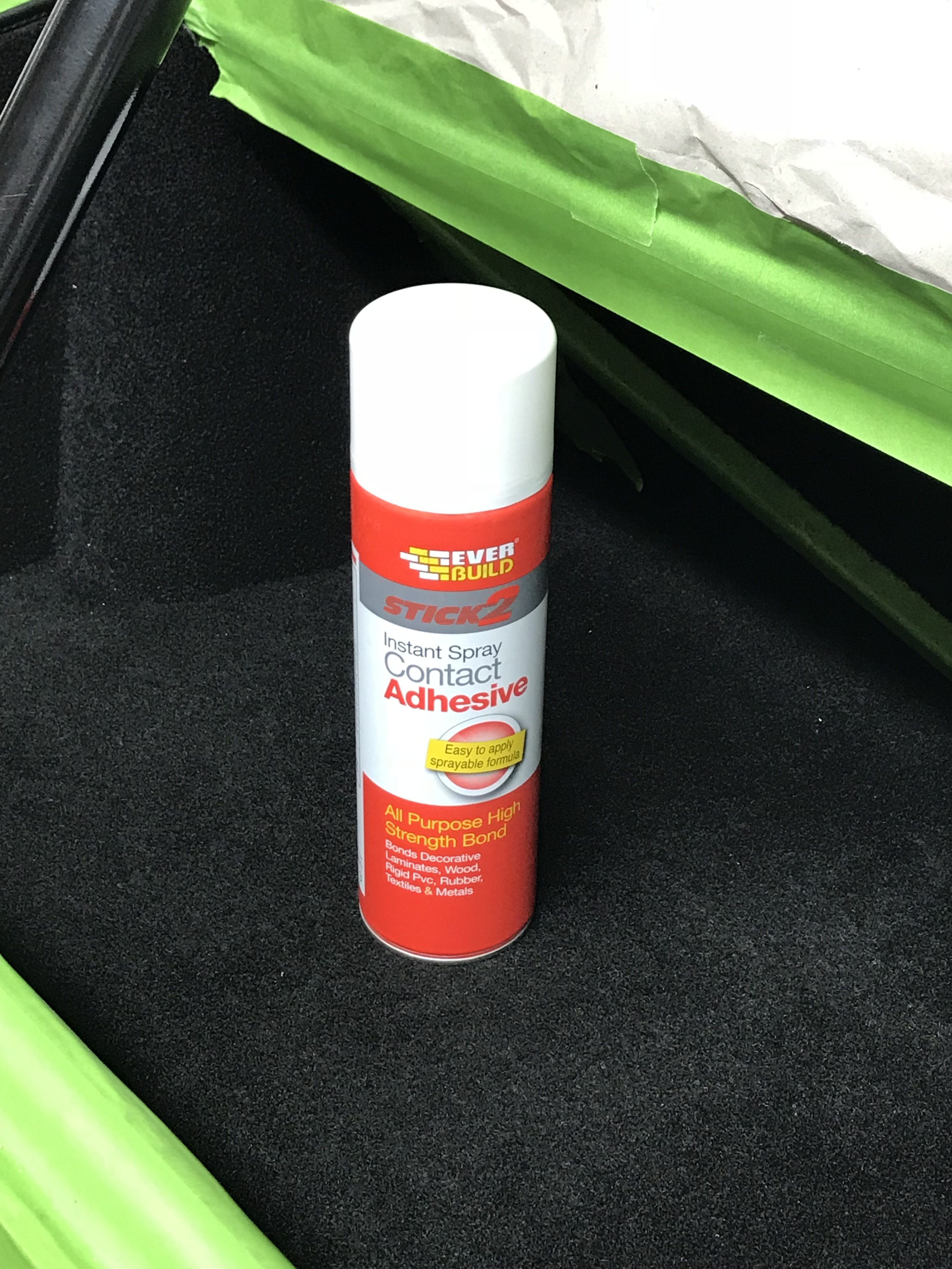
I’m using a spray can of Ever Build Stick2 Instant Contact Adhesive on the carpets.
The directions on the can talk about “permanent” and “semi-permanent” applications. I was going for a permanent install and so applied adhesive to both sides of the contact area and applied the carpet to the area relatively quickly – i.e. within a minute. Having said that, I didn’t apply adhesive all the way down the firewall behind the seats. I only went as far as the transmission tunnel. That meant I had a good contact at the top of the firewall but just a “tacked” install at the bottom where it didn’t matter. I think that if I end up having to take the carpets out then it will be a “rip and replace” but just in case that’s not what happens I thought I’d make it easier to extract the carpets where they can’t be seen… at the risk that the semi-tack approach stops tacking and the carpet comes away from the metal in that area.
Personally I found the application of the spray adhesive to be pretty controllable and accurate. As long as I didn’t try and spray an edge on my first spray from the can… I could then judge my aim more accurately for the edge sections. I also did all my carpet side spraying outside on a piece of cardboard (see later image of transmission tunnel carpet being sprayed). I did resolve, though, to mask in the boot, when I get to those carpets, the areas where the carpet tiles were much smaller and the chassis members were going to be prone to overspray.
Even with the “permanent” approach to the adhesive, I found I could peel the carpet off in sections and re-align a few times before getting the position just right.
Another thing I found… my universal solvent (petrol) did a good job of clearing up overspray of the adhesive on the pile side of the carpet, and… crucially… it did it without melting the carpet. It also worked well on the bodywork and chassis rails. I reasoned that anything that was meant to be installed that close to the fuel filler (bodywork, chassis AND carpet) was going to be petrol safe.
I had to do a little slicing and dicing on the firewall carpet around the transmission tunnel to get it to sit right. Just nicking the corners where the carpet met the tunnel was all I did. I was tempted to trim the carpet here but in the end I decided to leave that for another day – much easier to remove later than to add it again if I changed my mind.
Next up were the transmission tunnel walls. Again I went for a permanent adhesive approach, spraying both sides of the application area.

Then just a bit of trimming. As the tunnel top was going in and I’d tried a test fit… it seemed to be tight. So removing excess carpet from the top of the transmission tunnel seemed to make sense.
Another day over. I almost feel deflated that the major mechanical stuff has been done now. It seems to be cosmetics now. Though, of course, I may be counting my chickens before the fat lady has sung… I still need to start the engine and that might entail ripping everything apart again if it doesn’t work!

Leave a Comment