
To test out my theories and the code I’d been writing, I needed a simple test and a way to make sure the code (and I) was doing what I thought it should be.
The code part was easy, take the JSON files I’d created from the Easimap EC2 file and use it to ask for some simple data from the car.
As it turns out the “checking the code” part was also fairly straight forwards. I’ve talked about the Saleae Logic Analyzers in the past and how good they are. It also turns out that one of the software decoder modules they ship as standard is a CAN bus decoder. The idea is that you capture an analysis trace and then get the analyser software to decode the trace as CAN bus.
Saleae also have instructions on how to set up a CAN bus capture. They say that in most cases you can connect the analyser to CAN-L and set the analyser input to be high voltage (3.3v) and away you go.
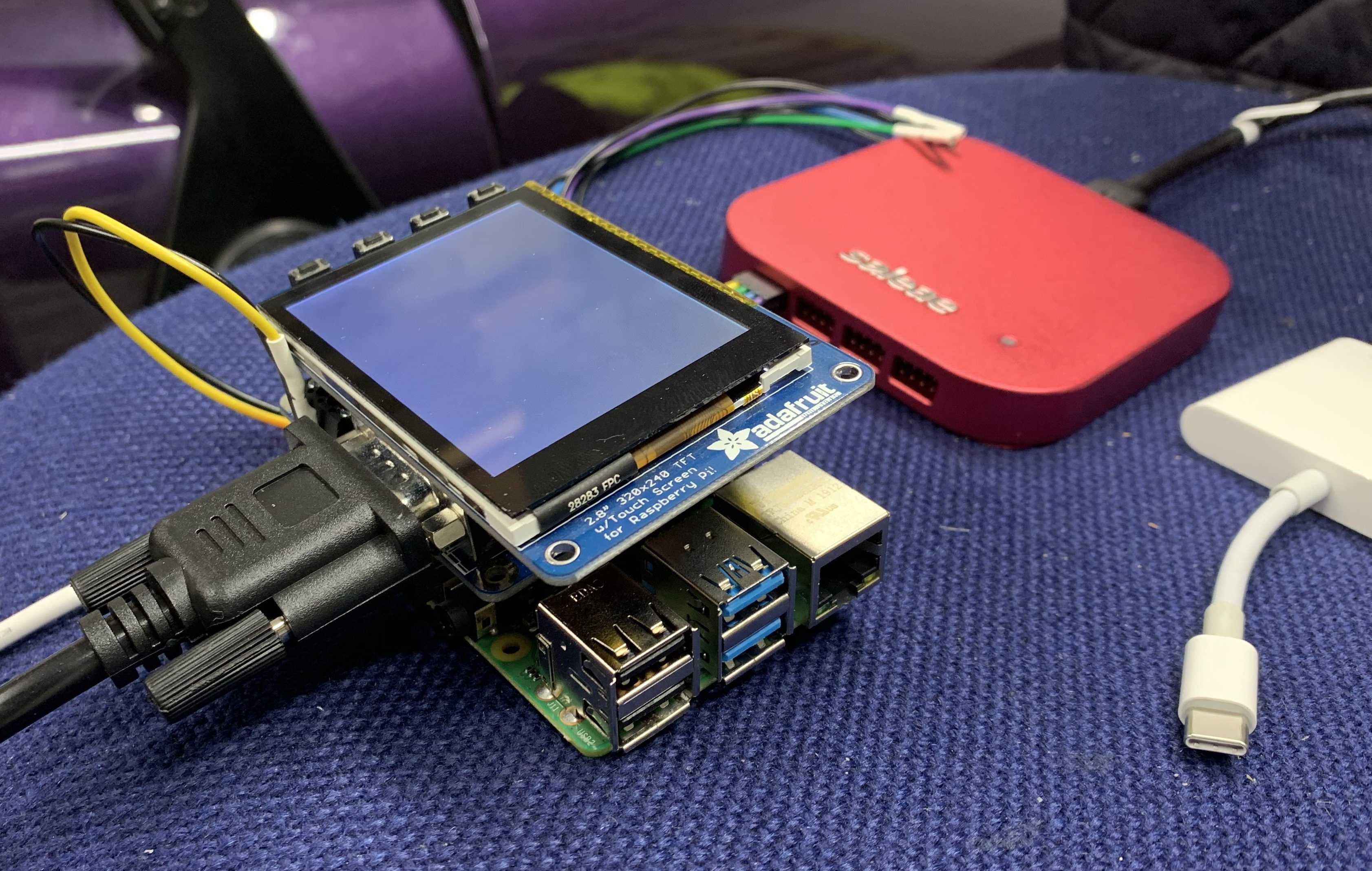
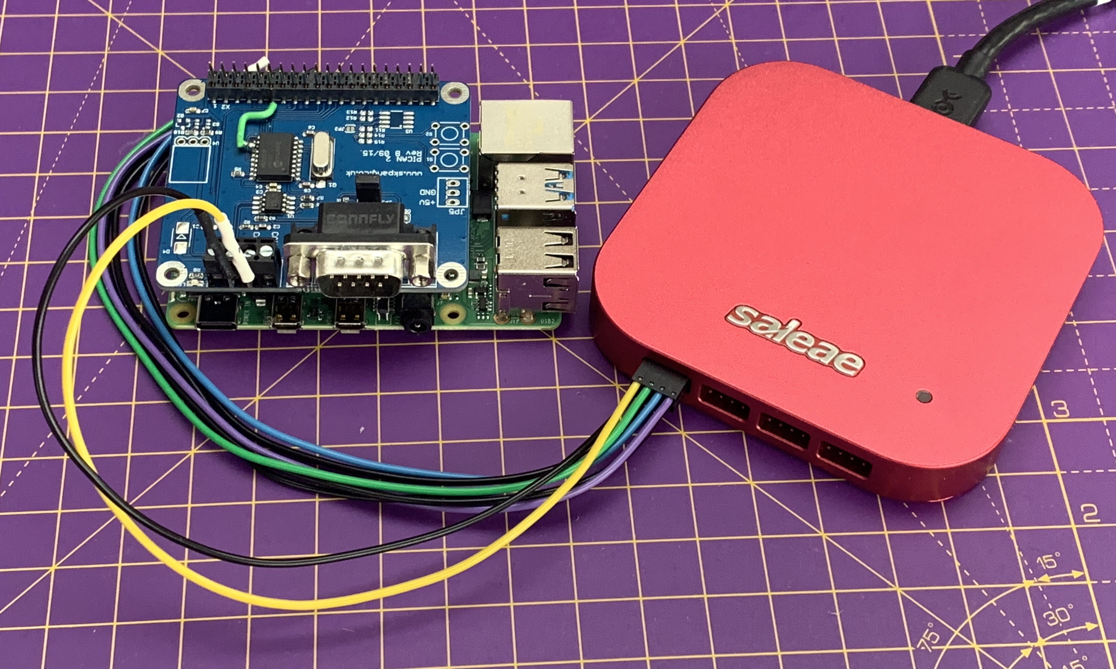
You’ll notice that there’s also a TFT LCD sat on top of the Pi, that’s for a later project.
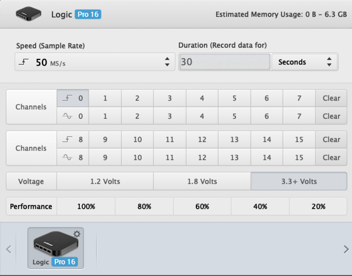
Analyzer Setup
With the analyser input set to 3v3 and a 50MHz sample rate I could capture the 1MHz activity on the CAN bus. I tried some captures at slower sample rates but they weren’t so reliable – clearly the analyzer needs to significantly oversample the signal to get the timing right.
Just for completeness, here’s a picture of the analyser leads connected to the PiCAN2…

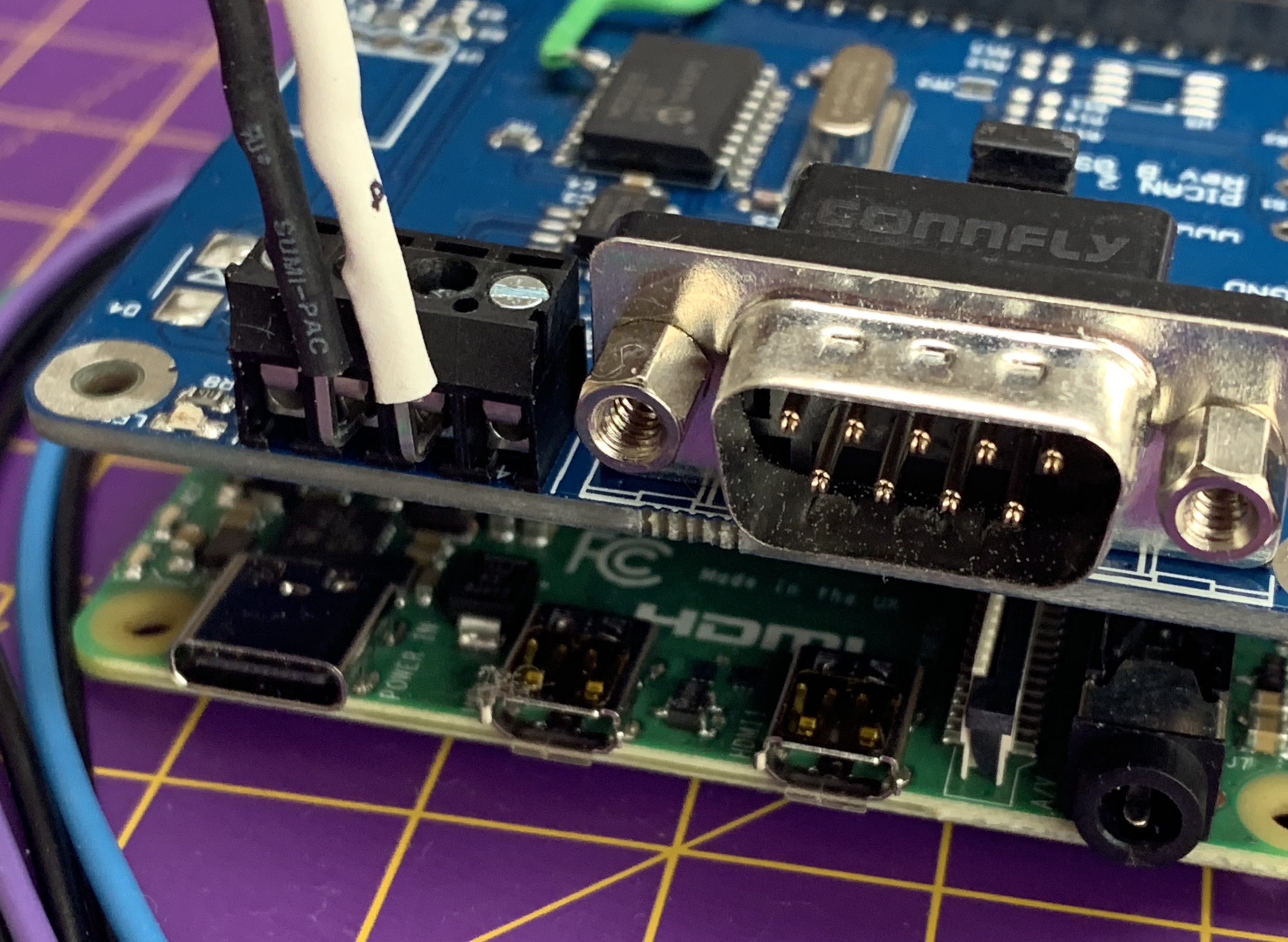
Here’s a closeup of the connections…
Anyways, that setup is well within the capabilities of the Saleae and gave very reliable results.
Test Code
Just to check my theories I wrote this simple app to pull just a few data samples from the car’s ECU. I started with RT_ENGINESPEED (Engine RPM) and got back the result I was expecting (i.e. 0 RPM, as the car wasn’t running).
Here’s the code, which can also be found here.
# TestECU
# Application for testing python-isotp-mbe class
#
# 2019-08-26 John Martin
#

import logging
import argparse
import json
import pprint
import mbe
import curses

version = "0.1"

if (mbe.test_mode):
  variables_to_follow = [
      'RT_ENGINESPEED',
    'RT_AIRTEMP1(LIM)',
    'RT_COOLANTTEMP1(LIM)',
    'RT_BATTERYVOLTAGE(LIM)',
    'RT_SOFTCUTTIME',
    'RT_HARDCUTTIME'
  ]
else:
  variables_to_follow = [
    'RT_ENGINESPEED'
  ]

def main():
  parser = argparse.ArgumentParser(prog='mbepcap2txt', description='Takes an pcap with ISOTP formatted MBE transactions and makes it human readable.')
  parser.add_argument('--interface',     '-i',                   help='The can interface to open', required=True)
  parser.add_argument('--variables',     '-v',                   help='Input MBE variables filename', required=True)
  parser.add_argument('--query_id',      '-q',                   help='CAN query ID (default 0x0cbe1101)', default=0x0cbe1101)
  parser.add_argument('--response_id',   '-r',                   help='CAN resdponse ID (default 0x0cbe0111', default=0x0cbe0111)
  parser.add_argument('--loglevel',      '-l',                   help='Logging level to show', choices=['INFO','DEBUG','WARNING', 'ERROR', 'NONE'], default="ERROR")
  parser.add_argument('--logfile',       '-f',                   help='If set logging will be sent to this file')
  parser.add_argument('--version',       '-V', action='version', version='%(prog)s '+version)

  args = parser.parse_args()

  logging_level = getattr(logging, args.loglevel, None)
  logging.basicConfig(level=logging_level, filename=args.logfile, filemode='w')

  ecu = mbe.mbe()

  ret = ecu.set_options(args.variables, args.query_id, args.response_id, args.interface)
  if(not ret):
    logging.error("Unable to set options")
    exit()

  if(ecu.add_variable_list_to_follow(variables_to_follow) != len(variables_to_follow)):
    logging.warning("Ooops, didn't add all the vars I wanted to")
  else:
    logging.info("Added all the variables we expected")

  ecu.bind()

  results = dict()
  if (ecu.process_all_pages(results) != False):
    logging.debug(pprint.pformat(results))

if __name__ == '__main__':
  main()
When we run the code above it makes a single request to the car for Engine RPM and displays the results. Here are the ISOTP CAN bus packets for this test:
REQUEST: 0100000000f87c7d<br>RESPONSE: 810000
As you can see in first packet, there’s a data request (0x01) to page 0xf8 with 0x7c and 0x7d as the requested data address.
Then in the response packet there’s a data response (0x81) with 0x0000 as the RPM. Bingo! And because the car engine wasn’t running at the time, a response of zero RPM makes perfect sense!
Here’s the 3 raw CAN bus frames that correspond to those ISOTP packets:
#     CAN ID     Data
[290] 0x0cbe1101 10 08 01 00 00 00 00 f8
[291] 0x0cbe1101 21 7c 7d
[292] 0x0cbe0111 03 81 00 00 00 00 f8 7c
And here’s what that looked like in the logic analyser. The three images are for each of the three CAN bus frames (you might need to click on the images to see them full scale)…


You can see details of the CAN bus protocol in full technicolor. The analyser software doesn’t show the start but you can see the ID, data and CRC. A more detailed discussion on the CAN bus protocol can be found in this post.
So my software is able to send a good ISOTP CAN bus request to the car and we get a good response back.
It Works!
So… it works! We’ve figured out how the three communications protocols work that these ECUs seem to use. There may be more to know but we can now use the more complicated protocol used by Easimap and dig deeper into the ECU.
Now lets summarize all we know about the various protocols.

Leave a Comment